13
Connector repair
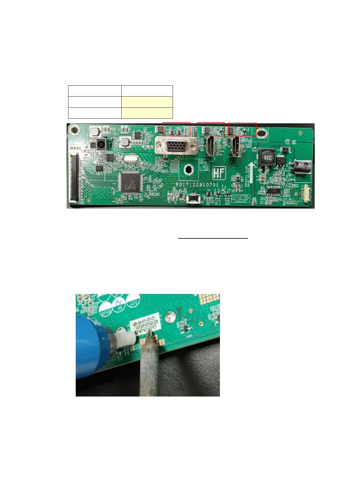
This procedure includes HDMI and VGA connectors.
The connectors are on the main board (board part number R353200920150
The connectors identifiers are as follows:
B
efore repairing connectors, follow these steps:
▲ Prepare the monitor for disassembly. See Preparation for disassembly o
n page 12.
VGA P100
Repair the VGA connector:
1) Use a hot air gun to melt the solder on the pins. Pin solder with soldering iron and absorber. You can gently
push down with the soldering iron once everything is molten to move the P100 out of the through holes.
2) L
ift the P100 connector from the PCB..
3) Place the new component on the PCB. Be sure that it matches the PCB footprint.
4) Solder the new component.
 Loading...