lp-505 Rev. 000 Rel. 015 Date 1.7.20
16
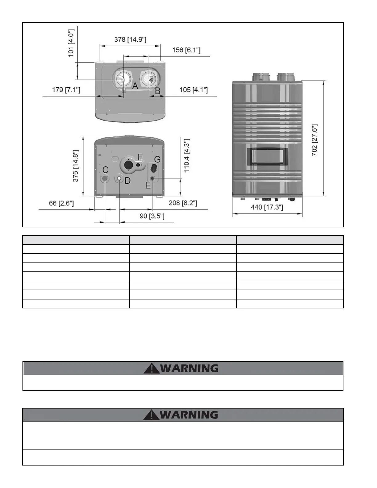
Description Diameter
A Exhaust Outlet Adapter 3”
B Air Intake Adapter 3”
C Gas Inlet Adapter 3/4” NPT
D DHW Outlet Adapter 3/4” NPT
E DHW Inlet Adapter 3/4” NPT
F Condensate Adapter 1/2” NPT
G DHW Inlet Filter N/A
Table 11 - 199 Model Adapter Specications
Figure 4 - 199 Model Dimensions
Field Wiring and Power Switch – Each water heater is supplied with a power switch to cut o power. The water heater is also equipped with
two front mounted terminal strips. These terminal strips are separated into low and line voltage to ease system wiring.
Condensate Trap and Hose Assembly – Each water heater has a built-in condensate trap to control the discharge of condensate produced
by the water heater during normal operation. A corrugated condensate hose is also provided to ensure proper drainage of condensate into
the pump or drain.
J. Wall-Mounting
The water heater may be installed on any suitable internal wall (suitable sound-proong may be required when installing onto a stud partition
wall).
The water heater must be installed on a wall that can bear its weight (more than 88 lbs. when fully plumbed and full of water). Installing the
water heater on a wall which cannot support its weight could result in property damage, personal injury, or death.
This water heater is too heavy for one person to lift. It is highly recommended to install the water heater with two people. Use caution as
to not drop the water heater, which could damage the water heater and cause property damage and/or severe personal injury. Verify that
the water heater is properly and securely mounted before leaving unsupervised. Failure to comply with the above and properly mount the
water heater could result in substantial property damage, severe personal injury, or death.
This wall mounting system is not seismic rated and should not be applied as such. Failure to comply with the above and properly mount the
water heater could result in substantial property damage, severe personal injury, or death.

 Loading...