lp-505 Rev. 000 Rel. 015 Date 1.7.20
47
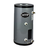
C. Additional Precaution for Excess Flow Valve (EFV)
If an excess ow valve (EFV) is in the gas line, check the manufacturer’s
minimum and maximum ow capacity ratings. An improperly sized
EFV will not allow for a full ow of gas to the water heater and will
cause the water heater to malfunction. See Figure 43.
Figure 43 - Excess Flow Valve (EFV)
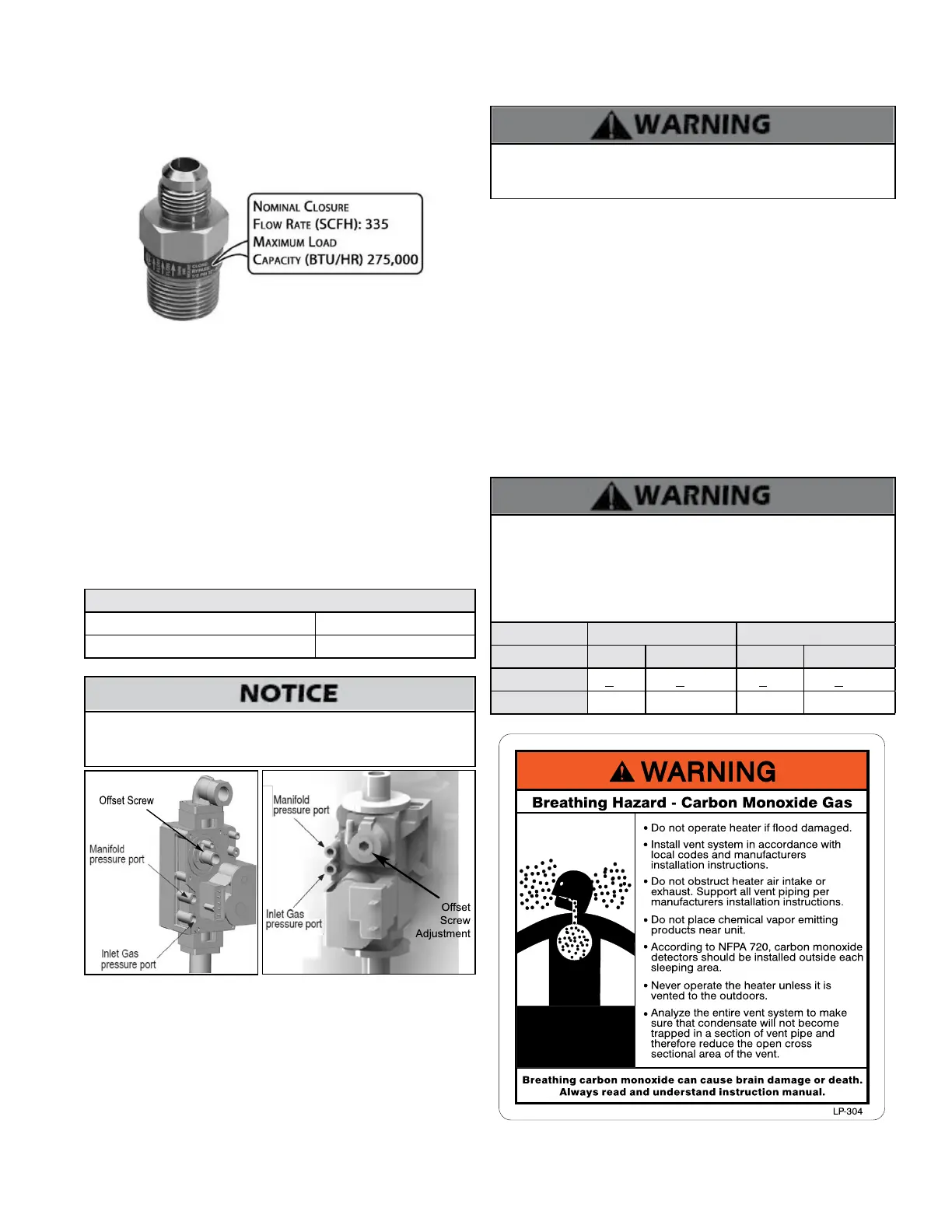
D. Checking Gas Pressure at the Water Heater for Proper
Operation
NOTE: Refer to Figures 44 and 45 when checking gas pressure.
Loosen the bolts before checking the gas inlet pressure.
1. The water heater and its individual shuto valve must be
disconnected from the gas supply piping system during any
pressure testing of the system at test pressures greater than ½ psi
(3.5 kPa).
2. The water heater must be isolated from the gas supply piping
system by closing its individual manual shuto valve during any
pressure testing of the gas supply piping system at test pressures
equal to or less than ½ psi (3.5 kPa).
The minimum and maximum inlet gas line pressures must meet the
requirements shown in Table 26.
Natural or LP Gas
Minimum Pressure 3.5” WC
Maximum Pressure 14”WC
Table 26 - Gas Pressure Requirements
Do not re (operate) the water heater until all connections have
been completed and the heat exchanger is lled with water. Doing
so will damage the water heater and void the warranty.
Figure 44 - 150 Model - Gas
Valve Detail
E. Setting and Verifying the Combustion Setting
1. After the water heater has red, ip DIP switch seven (7) to the
ON position (low re). Proceed to check heater combustion values.
NOTE: Use a calibrated combustion analyzer to ensure CO and CO2
values are within the range shown in Table 27.
If the readings obtained are lower or higher than the combustion
readings in Table 27, use a 4mm Allen key to adjust the oset screw
in a clockwise (positive) or counterclockwise (negative) direction
(approximately 1/4 turn). See Figures 44 and 45. Check your
It is required to use a calibrated combustion analyzer to verify nal
adjustment according to the combustion chart (Table 27). Failure to
do so could result in serious personal injury or death.
combustion values. Repeat this procedure until the values obtained
on the calibrated combustion analyzer agree with those stated in Table
27.
It is very important that the combustion system be set within the
recommended CO measurements listed in Table 27. Visually looking
at the burner does not determine combustion quality. Failure to
measure combustion with a calibrated Combustion Analyzer and
set the throttle within the recommended CO measurements could
result in property damage, severe personal injury, or death.
Natural Gas LP Gas
Fan Speed Low High Low High
CO PPM <60 <200 <60 <200
CO2 (%) 8 - 10 8 1/2 - 10 1/2 9 - 10 1/2 9 1/2 - 10 1/2
Table 27 - Combustion Settings
NOTE: If the heater makes a whistling sound (harmonics) at low re,
adjust the oset screw in a clockwise (positive) direction (approximately
1/8 turn). Check your combustion values and ensure they agree with
those stated in Table 27 before proceeding.
2. When low re settings have been obtained, ip DIP switch seven
(7) to its original (OFF) position. This will return the heater to normal
operation.
3. Flip DIP switch six (6) to ON (high re). Again check combustion
readings with a calibrated combustion analyzer.
NOTE: DO NOT adjust the gas valve oset screw at high re. The oset
screw is only used to adjust combustion values at low re.
4. When complete, ip DIP switch six (6) to its original (OFF) position.
This will return the heater to normal operation.
5. Allow heater to operate normally. Ensure it is operating properly.
6. Reinstall the heater front cover.
7. Use a Phillips Head screwdriver to reinstall the heater top cover.
Figure 45 - 199 Model - Gas Valve
Detail

 Loading...