33
LP-179 REV. 11.26.14
2” PVC CONCENTRIC VENT TERMINATION KIT
3” PVC CONCENTRIC VENT TERMINATION KIT
2” STAINLESS STEEL VENT TERMINATION KIT
3” STAINLESS STEEL VENT TERMINATION KIT
4” STAINLESS STEEL VENT TERMINATION KIT
Table 8
H. VENTING DRAWINGS
1. DIRECT VENT INSTALLATION OF EXHAUST VENT AND INTAKE PIPE
If installing a direct vent option, combustion air must be drawn from the outdoors directly into the water heater intake, and exhaust must
terminate outside. There are three basic direct vent options detailed in this manual: 1. Side Wall Venting, 2. Roof Venting, and 3.
Unbalanced Venting.
Be sure to locate the heater such that the exhaust vent and intake piping can be routed through the building and properly terminated.
Different vent terminals can be used to simplify and eliminate multiple penetrations in the building structure (see Optional Equipment in
Venting Section). The exhaust vent and intake piping lengths, routing and termination methods must all comply with the methods and
limits given in the Venting section, Part 5 of this manual.
When installing a combustion air intake from outdoors, care must be taken to utilize uncontaminated combustion air. NOTE: To
prevent combustion air contamination, see Table 1 – Contaminant Table.
Take extra precaution to adequately support the weight of vent pipes terminating through the roof. Failure to properly support roof
terminated vent piping could result in property damage, serious personal injury, or death due to flue gas leakage.
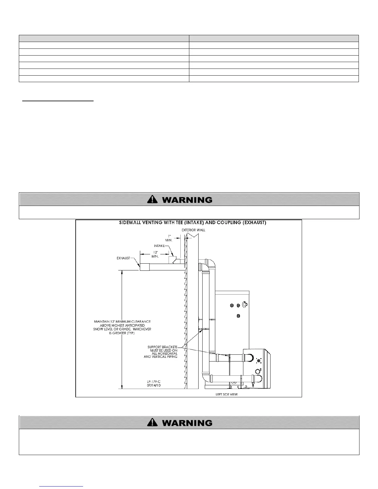
Figure 15 – Sidewall Venting - NOTE: This drawing is meant to demonstrate system venting only. The installer is responsible for all equipment
and detailing required by local codes.
All vent pipes must be glued, properly supported, and the exhaust must be pitched a minimum of ¼” per foot back to the heater to allow
drainage of condensate. When placing support brackets on vent piping, the first bracket must be within 1 foot of the water heater and
the balance at 4 foot intervals on the vent pipe. Heater venting must be readily accessible for visual inspection for the first three feet
from the heater.

 Loading...