lp-770 Rev. 000 Rel. 000 Date 6.21.21
12
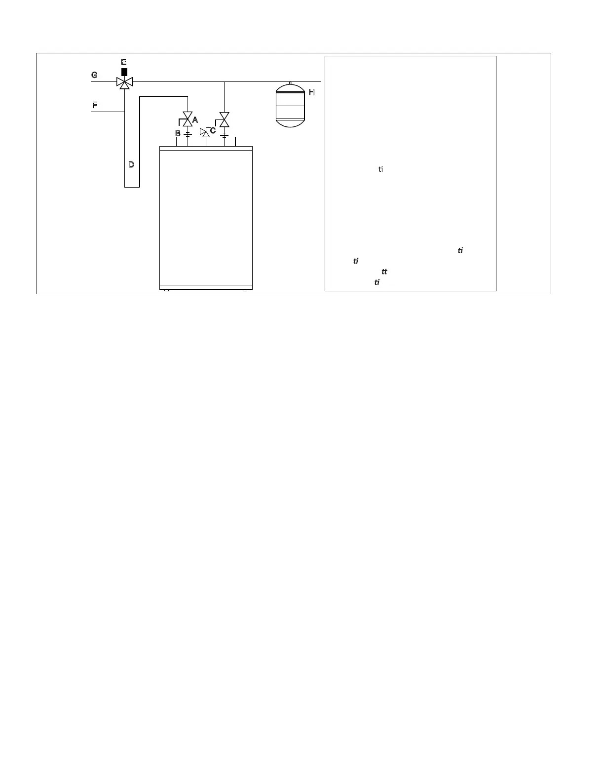
I. Applications
Figure 5 - Mixing Valve Application
NOTES:
1. Minimum pipe size should match connection size. Upsize pipe accordingly if greater ow is required.
2. A thermal expansion tank suitable for potable water must be sized and installed within this piping system between the backow preventer
and the cold water inlet.
3. All circulators should have an integral ow check.
4. Drains and check valve between the heating appliance and water heater will assist in purging air from system.
5. This drawing is meant to demonstrate system piping only. The installer is responsible for all equipment and detailing required by local
codes. In Massachusetts, you must install a vacuum relief valve per 248 CMR.
6. Mixing valve application is optional, but recommended to help prevent scalding.
A
B
C
D
E
F
G
H
Legend
A Ball Valve—Typical
B Dielectric Union—Suggested
C Temperature & Pressure Relief Valve
D Heat Trap Loop—Suggested
E Thermosta
c Mixing Valve –Suggested
F High Temperature Outlet
G Mixed Temperature Outlet
H Expansion Tank in Cold Water Supply
Note: For drawing clarity, addi
onal
isola
on valves and other accessories have
been omi
ed. Follow normal piping
prac
ces when installing tank.