lp-65 Rev. 1.6.15
11
3. After ensuring there are no leaks within the system, ush the
system to clear any soldering residue. Many soldering uxes
contain Zinc Chloride, which can corrode stainless steel.
Draw at least three times the volume of the water heater to
properly ush the system.
4. Initiate a call for hot water. Ensure each zone valve or circulator
operates only when its thermostat calls for heat. Purge each
zone of air to ensure proper operation.
5. Set the water heater to the desired temperature. Boiler
high limit should be set at least 20
o
F higher than the heater
temperature. Set
the low limit of the
boiler control at the
minimum setting -
this will call the burner
on only to satisfy the
tank control.
A water heater
temperature
setting of 120
o
F
is recommended.
However, a lower
temperature setting
may be required to
comply with local
and state codes for
normal operation. The
dierential is xed 3
to 5
o
F. Installation
conditions may
require a higher or
lower temperature
setting. A mixing valve in conjunction with a high temperature
setting may be used for high demand applications (spas, hot
tubs, whirlpools).
6. When the system is completely ushed, purged of air, and
the temperature is set, turn on the boiler. Observe operation.
Ensure the boiler shuts down after the indirect water heater set
point is satised.
1. Fill the water heater by opening the cold water shut-o valve.
Purge air from the system by opening a hot water outlet at a
xture in a kitchen or bathroom. When water ows freely from
the outlet, the system is purged.
Part 5 - Start-Up and Operation
When lling the water heater, open a hot water tap to release air
in the tank and piping to ensure proper water heater operation.
Failure to ensure the water heater is full before turning on the
system will result in damage to the water heater, and could
result in property damage. Such damages ARE NOT covered by
warranty.
2. Check the system for leaks.
Fix any leaks before continuing the installation. Failure to do so
could result in property damage or personal injury.
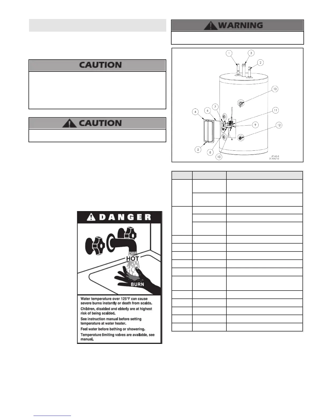
Risk of scald injury increases as you increase water
temperature.
Figure 15 - Replacement Parts
Item # Part # Description
1
6075P-002
Hot Water Outlet
(SSC-35, SSC-50)
6075P-008
Hot Water Outlet
(SSC-80, SSC-119)
2
6075P-001 Cold Water Dip Tube (SSC-35)
6075P-003 Cold Water Dip Tube (SSC-50)
6075P-009
Cold Water Dip Tube
(SSC-80, SSC-119)
3 6075P-043 Magnesium Anode Rod
4 6075P-187 Electrical Box Cover
5 6075P-006 #8 X 3/4 Self Tapping Screws (2)
6 6075P-053 Fiberglass Insulation
7 6060P-952 Plastic Protective Cover
8 6060P-632
5/16 - 18 Hex Nut - Thermodisc
Mounting Clip
9 6060P-630 Green Ground Wire W/ Ring
10 6060P-633 Thermodisc Mounting Clip
11 6060P-1009 Thermostat Control
12 2500P-0092 Drain Valve
13 TP1000 Relief Valve
Table 5 - Replacement Parts List
 Loading...