lp-65 Rev. 002 Rel. 010 Date 10.11.19
9
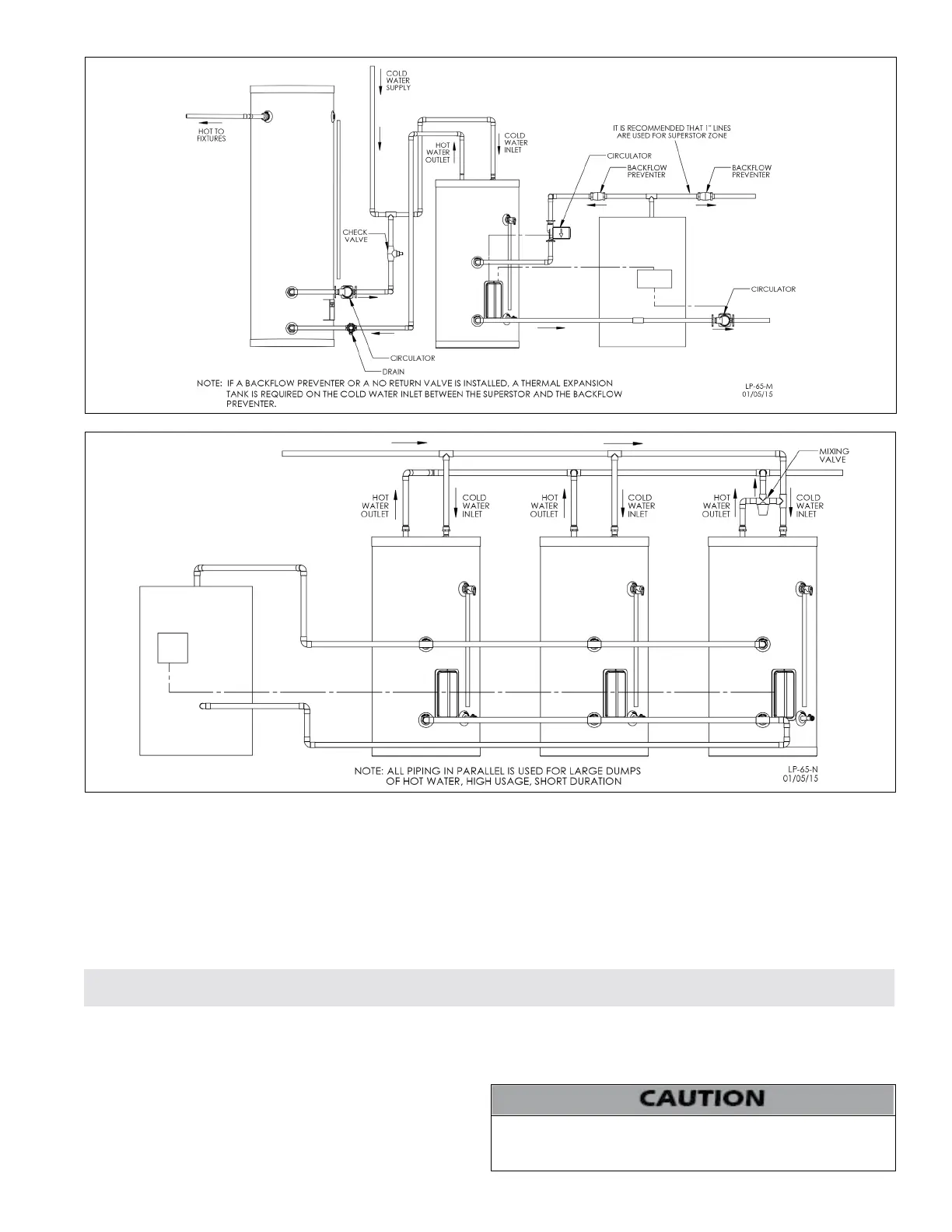
Figure 7 - Installation with Storage Tank
NOTES:
1. Minimum pipe size should match connection size. Upsize pipe accordingly if greater ow is required.
2. A thermal expansion tank suitable for potable water must be sized and installed within this piping system between the backow preventer
and the cold water inlet.
3. All circulators should have an integral ow check.
4. Drains and check valve between the heating appliance and water heater will assist in purging air from system.
5. This drawing is meant to demonstrate system piping only. The installer is responsible for all equipment and detailing required by local
codes. In Massachusetts, you must install a vacuum relief valve per 248 CMR.
6. Mixing valve application is optional, but recommended to help prevent scalding.
Figure 8 - Multiple Tank Installlation
Part 4 - Heater Control and Wiring
A. Control
A surface mounted control is provided and mounted inside of the
control access compartment. There is an insulation blanket under
the control access cover to ensure accurate readings of water
temperature. The control is factory set at 120
o
F for your safety (see
scaled danger warning below). The dierential is xed at 3 to 5
o
F
(not adjustable).
B. Wiring
Wiring is to be done in accordance with all applicable local and state
When wiring the water heater and controls be sure to label all wires
to ease future maintenance. Wiring errors can cause improper and
dangerous operation.
codes. Turn o all power related to the boiler before starting any wiring
procedures. It is recommended that a disconnect switch be installed
between the boiler control and the water heater.
 Loading...