3
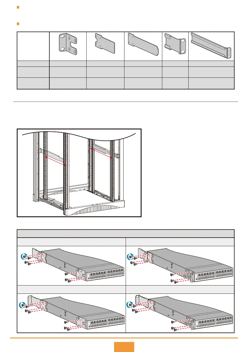
If the distance between front and rear mounting rails is not within the required range, install guide rails or a
tray (self-provided) in the cabinet/rack to support the chassis.
Switch and mounting bracket mapping table.
Installation Procedure
Measure the distance between the front and rear mounting rails (distance A in the figure below). The type
and installation method of mounting brackets and matching guide rails vary depending on this distance.
(See values in the following table.)
Step 1
Fix mounting brackets to the switch with M4 screws.
Step 2
CE8850-32CQ-EI
CE7800&6800
(600 mm deep)
Mounting
brackets and
guide rails
Supported
Not supported
Supported
Not supported
Supported
Supported
Supported
Supported
Supported
CE6800&5800
(420 mm deep)
Supported SupportedSupported Supported Supported
Supported
Mounting bracket A Mounting bracket B Mounting bracket C Guide rail E Guide rail F
Distance A
Distance A
310 mm-351 mm 369 mm-410 mm
438 mm-479 mm 497 mm-538 mm
Mounting bracket and guide rail bundles for the CE8850-32CQ-EI&6800&5800 (420 mm deep)
Mounting bracket A
+ Mounting bracket B
+ Guide rail E
Mounting bracket A
+ Mounting bracket B
+ Guide rail E
Mounting bracket A
+ Mounting bracket B
+ Guide rail E
Mounting bracket A
+ Mounting bracket B
+ Guide rail E
 Loading...