The switch must use the power modules and fan modules matching the product model.
The power modules and fan modules used in the switch must have the same airflow direction.
Power modules with different airflow directions or power values, AC and DC power modules, or fan modules with different
airflow directions cannot be used in the same chassis.
FAN-060A series fan modules can only be installed in CE6850HI, CE6850U-HI, CE6855-48T6Q-HI, CE6856-48T6Q-HI and CE6875EI.
Installing them in other switch models may damage the fan modules or switches.
CAUTION
6.1 Selecting Power Modules and Fan Modules
6.2 Installing Power Modules and Fan Modules into the Chassis
6
6 Installing Power Modules and Fan Modules
Before You Start
If the switch is delivered with the power modules and fan modules installed in the chassis, you do not need to
install the power modules and fan modules again.
Before installing a power module or fan module, remove the filler panel in the slot.
If only one power module is used, install a filler panel in the other power module slot.
To ensure normal operating, the switch must have two normally running fan modules.
Do not remove the two fan modules from the chassis simultaneously. Replace a fan module within 3 minutes.
Front-to-back airflow: Power modules and fan modules with front-to-back airflow are identified by
a or flag. Air flows from the power supply side to the port side.
Back-to-front airflow: Power modules and fan modules with back-to-front airflow are identified by
a or flag. Air flows from the port side to the power supply side.
Step 3
Step 4
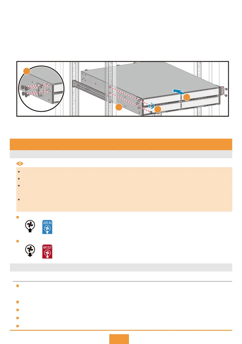
Install the front mounting brackets near the power supply side or port side depending on which side is
facing the front. In the following figure, the front mounting brackets are installed near the port side.
Install the switch in the cabinet.
a. Lift the switch onto the expandable guide rails by two persons.
b. Slowly push the switch into the cabinet until the front mounting brackets are closely attached to the
floating nuts on the mounting rails.
c. Secure the front mounting brackets on the mounting rails with M6 screws.
Step 5
Connect the ground cable to a ground point on the cabinet. The ground points of the CE8860, CE8861,
CE8868 and CE8850-64CQ-EI are at the power supply side of the switches.
a
c
b
3
 Loading...