7
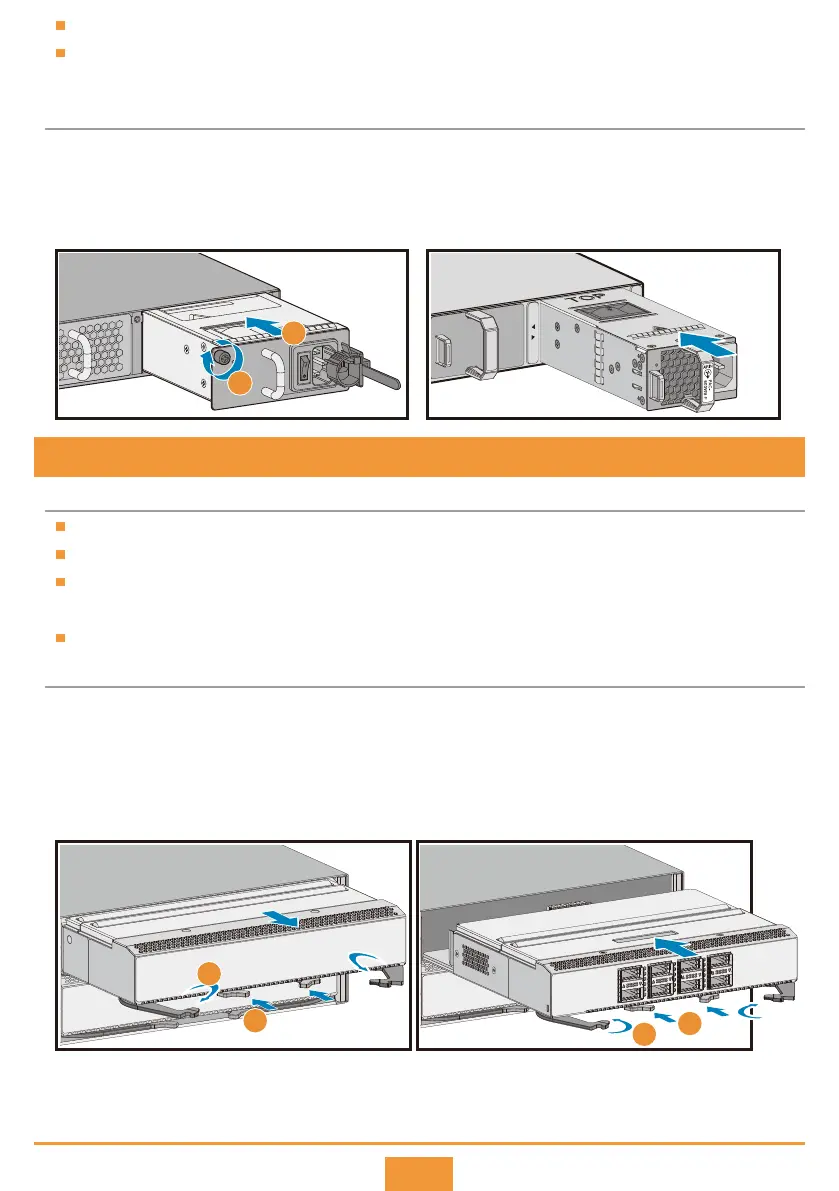
Press the two green locking clips in the middle of the filler panel to eject the ejector levers.
Turn the ejector levers outward and slowly pull the filler panel out.
Press the two green locking clips in the middle of the card to eject the ejector levers.
Slowly push the card into the slot, and then turn the ejector levers inward to lock the card in the slot.
When the card is completely seated in the slot, the ejector levers will buckle with the locking clips.
Step 1
Step 2
Step 3
Step 4
Installation Procedure
7 Installing a Card into the Chassis
Insert the power module into a power slot.
Tighten the captive screw on the power
module panel.
Insert the power module into a power slot. When the
power module is completely seated in the slot, the lock
is locked automatically.
Step 1
Step 2
Installation Procedure
Power modules fixed using a captive screw and a lock are installed differently.
Power modules and fan modules are hot pluggable. A fan module is installed the same way as a power
module fixed with captive screws.
Power module secured by a captive screw Power module secured by a lock
Before You Start
PAC-150WA
STATUS
1
2
PWR1 PWR2
STAT
1
2
3
4
1
2
1
2
3
4
3
4
Only the CE8860, CE8861 and CE8868 switches have extended slots for card installation.
Install a filler panel in a vacant slot.
Slowly push a card into the slot. If you feel resistance or find the card inclined, pull the card out and push it
into the slot again. Forcing the card into the slot may damage connectors on the card and backplane.
All cards are hot swappable.
 Loading...