1c
Checking components
The following installation tools are required:
Phillips screwdriver (M3 to M6)
Flat-head screwdriver (M3 to M6)
Diagonal pliers
Floating nut mounting bar
A storage system power failure may cause devices connected to the
same circuit breaker to power off unexpectedly. Therefore, ensure
that the storage system power supplies have functioning circuit
breakers with the following amps:
AC power: not smaller than 10 A
DC power (not applicable to 5110 V5): not smaller than 30 A for
controller enclosures, not smaller than 18.5 A for disk enclosures
1 Installation Preparations
Only materials used in the installation process are listed here. The Packing List contains all materials required by the installation. The bag
containing the Packing List is attached to the outside of the carton.
Each controller of the OceanStor 5110 V5/5300 V5 is equipped with four GE electrical ports. Each controller enclosure of the OceanStor 5500
V5 is equipped with four SmartIO ports that do not support IP Scale-out networking. The following sections describe the process for installing
the OceanStor 5500 V5. The process for installing the OceanStor 5110 V5/5300 V5 is similar.
5110 V5 does not support high-density disk enclosures.
3
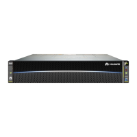
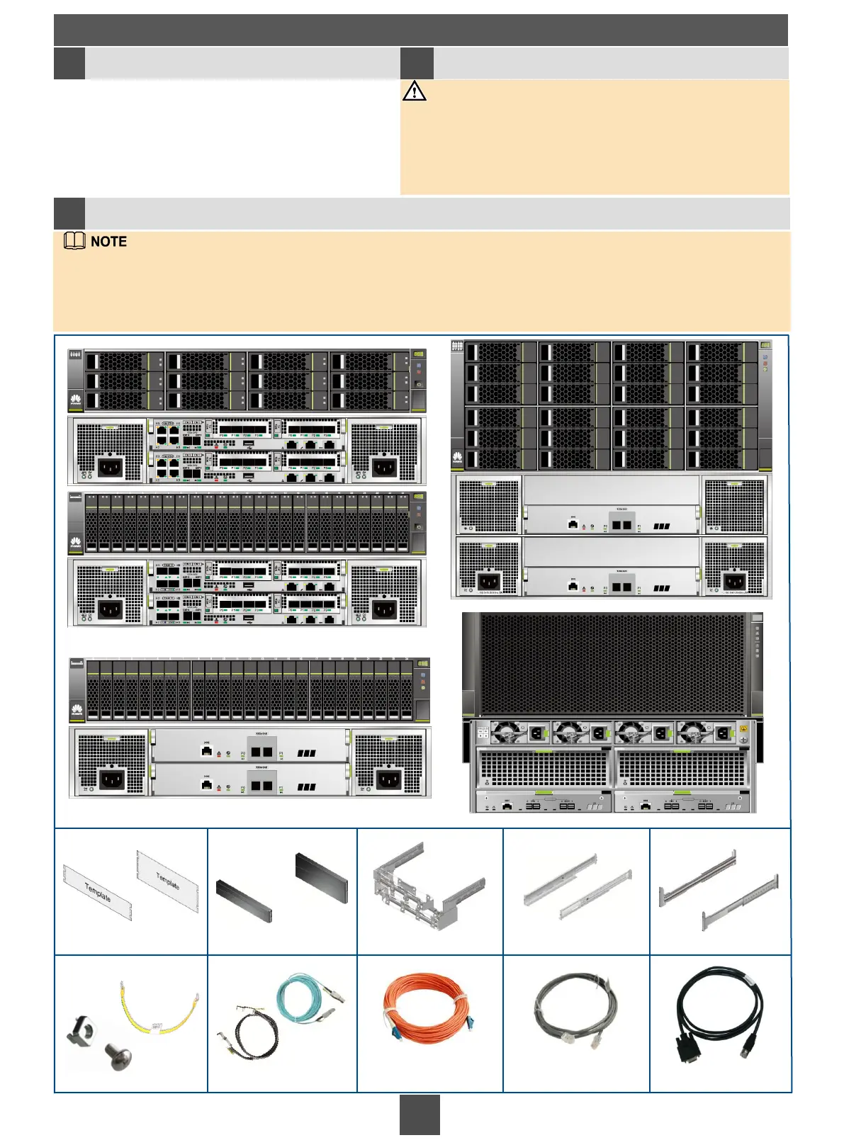
Disk enclosure (2 U)
Controller enclosure (2 U)
Installation template
(for 2 U devices)
Front panel of a
2 U device
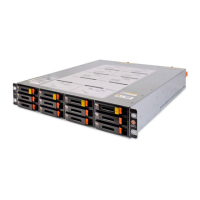
High-density disk enclosure (4 U)
Adjustable guide rails Ball bearing guide rails
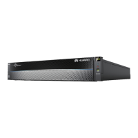
Disk enclosure (4 U)
Installation template (for
4 U devices)
Front panel of a 4 U
device
Checking installation tools Checking circuit breakers 1b 1a
NOTICE
Cable tray
Floating nut and M6 screw
Ground cable
Multi-mode optical fiber
cable
Network cable
Serial cable
Mini SAS HD optical
cable
Mini SAS HD electrical
cable

 Loading...