35
FIG. 5
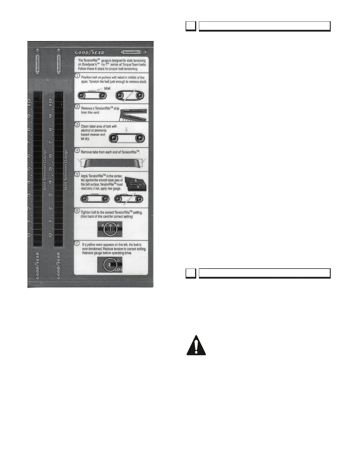
TensionRiteGage™,PartNo.191368
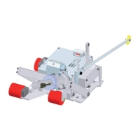
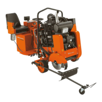
This saw has a parking brake on the rear drive wheel. It
is to be used as a passive parking brake. It is not to be
used for dynamic braking. Apply the brake only when
the machine is stationary. The brake can be engaged
manually while the engine is running. It will automatically
apply when the engine is shut off.
The brake can be overridden if the machine
has to be pushed. There is a bolt on the rear
of the motor, to release the brake turn the
bolt clockwise until it bottoms out. It must be
turned counter clockwise before the machine
is put back in service.
The hydraulic system on this saw is used to RAISE /
LOWER the Diamond Blade (2E) and to propel
thesawFORWARDandREVERSE,SteerthesawLEFT
andRIGHT,runtheCoolingFan,andreleasetheParking
Brake.TheRAISE/LOWERsystemasaDCLiftPump
mounted in the side of the hydraulic tank, two (2) lift
cylinders and a lowering valve. The lowering rate of the
saw can be adjusted with the Flow Control Valve which
is at the rear of the machine under the cowling.
The Steer and Fan system is powered from the hydraulic
gear pump mounted on the engine. Flow is directed to
thesteervalveandturningCLOCKWISEorCOUNTER
CLOCKWISEsendsowtoanactuator.Anyexcessow
is sent to the hydraulic motor to cool the radiator.
The propel pump is belt driven off the front of the engine
through an electric clutch. A cable control changes the
directionandspeedofowtothesinglereardrivewheel.
A dump valve and shuttle valve controls the release
pressure for the parking brake.
Excess oil is run through the water / hydraulic cooler to
keep oil temperature low.
Hydraulic Maintenance
• Thehydrauliclterislocatedatthefrontofthesteering
console.Itshouldbechangedaftertherst50hours
and then after every 300 hours of operation.
• Checkthehydraulicoillevelweekly.MaintainwithATF
oiltypeF.DONOTOVERFILL,checkoillevelONLY
when saw is level. 3” below top of tank.
11
HYDRAULIC SYSTEM
12
PARKING BRAKE
 Loading...