6
–
English
ASSEMBLING AND ADJUSTMENTS
Unpac
king
Illustration:
1 • 1
Assemb
ly
Illustration:
1 • 2
•
Fitting the tine blades. Illustrations only shows assembly
of the tine b
lades on the right side. Make sure that the
sharp edges face one side on both right and left side tines.
Please pay attention to distinguish the two Sub holders.
(Figure 1 - 7)
•
Fitting the connecting joint.
(Figure 8)
•
Fitting the drag bar.
(Figure 9)
•
Fitting the handle bar.
(Figure 10)
•
Adjust the hight of the handle and tighten the knobs
securely
.
(Figure 11 - 12)
•
Fitting the clutch control.
(Figure 13)
-
Turn to proper side and fasten the bolt.
• Fitting the lower tidy cover.
(Figure 14 - 15)
-
Tidy the cables.
- Fit the rubber holder properly.
- Fit the cover and fasten with bolt.
• Fitting the tine cover.
(Figure 16 - 20)
- Do not tighten the bolt immediately after installed.
- Install all 4 bolts and n
uts first, then tighten one by one.
• Fitting the shifting lever.
(Figure 21)
An
y dismantling operation must only be performed by an
author
ized service workshop.
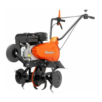
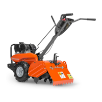
Description of the components
Illustration:
1 • 3
1
Engine
2 Tine cover
3 Handle
4 Extension cover
5 Blades
6 Drag bar
7 Upper tidy cover
8 Lever shifting
9 Bumper
10 Clutch control
11 Throttle control
12 Reverse control
13 Side cover
14 Lower tidy cover
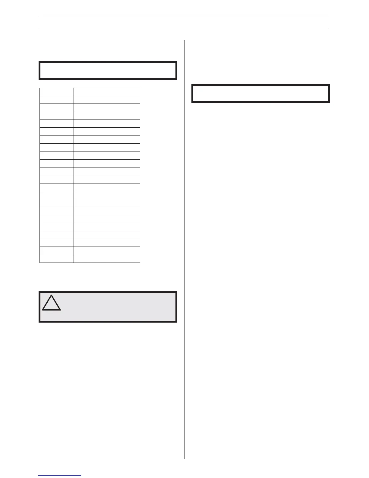
T
ype plate
Illustration:
1 • 4
1
Serial number
2 Article number
3 Model
4 Tilling scope
5 Tilling depth, mm
6 Gear shifting
7 Engine displacement
8 Engine oil Quality (viscosity):
9 Engine oil capacity
10 Gear box oil, quality
11 Gear box oil capacity
12 Nominal power
13 Net weight, kg
14 Fuel
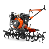
T
ransport wheel
Illustration:
1 • 5
Change the tines to wheels when tr
ansporting.
For more information about moving of the machine, see
section "Mo
ving".
IMPORTANT! Make sure to not cut the cables/wires or
scr
atch the machine when cutting the edges of the case.
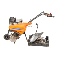
Ref
erences Content of the case
A
Engine par
ts
B Sub holder 1
C Holder main comp
D Lower tidy cover
E Drag bar
F Tine cover
G Tine cover bracket FR
H Lever shifting
I Blades
J Wheel
K Connector joint
L Extionsion cover
M Side cover
N Locking handle
O Tine cover bracket RR
P Rubber cable holder
Q Sub holder 2
R Connecting plate
S Hardware bag tines only
T Hardware bag
W
Tool bag
!
W
ARNING! Inappropriate assembly of this
rotary tiller could cause severe injuries.
Ensure that you follow all the instructions
carefully.
CA
UTION! After assembling the machine completly, tighten
the bolts and screws with modertion. Do not overtighten.
 Loading...