REV D 3-12 604466
Clutch life will be maximized if these procedures are
followed.
1. Engage the clutch o
nly when the throttle is set at
approximately 2/3 throttle and there is no load on the
blades. After clutch engagement, advance the engine
throttle to full rpm.
Engaging the deck clutch at high engine rpm or when
under heavy
load (in tall grass, for example) can cause
belts and/or electric clutch to slip, resulting in premature
wear or possible damage.
2. Disengage the clutch on
ly when the throttle is set at less
than 1/2 throttle.
Never disengage the clutch with the engine running at
hig
h rpm. Setting the throttle to less than 1/2 throttle
when disengaging the clutch will help extend clutch life.
Warranty will not be allowed for deck
clutches that fail due
to improper engagement and disengagement practices.
Deck Cutting Height Adjustment
Deck cutting height is adjustable in 1/4” (6.4mm) increments.
The holes in the height adjusting bar are spaced at 1/2”
(12.7mm) intervals. By turning the height adjusting stop around,
1/4” (6.4mm) increments can be attained due to the 1/4”
(6.4mm) plate that is part of the stop. Figure 3-12
EXAMPLE:
When the height adjusting stop is placed in the
3” (76.2mm) hole, with the 1/4” (6.4mm) plate facing to the
front of the unit, the cutting height is at 3” (76.2mm). When the
height adjusting stop is placed in the 3” (76.2mm) hole, with
the 1/4” (6.4mm) plate on the operator’s side of the hole, the
cutting height is at 3-1/4” (82.6mm).
The notch located at the rear of th
e height adjusting bar
engages the stop handle when the deck lift pedal is fully
depressed. This sets the deck in transport mode.
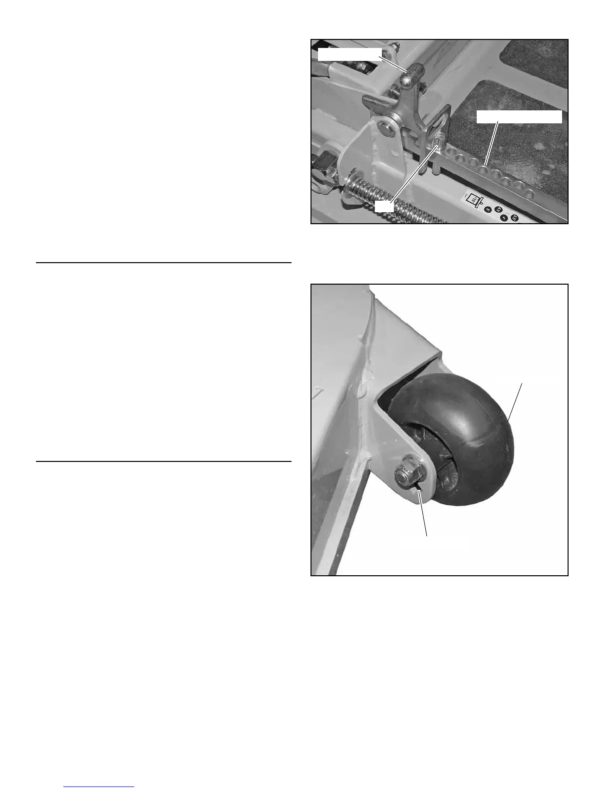
Anti-Scalp Wheels
Anti-scalp wheels are standard on Hustler
®
X-ONE i units.
These anti-scalp wheels are designed to minimize scalping
when mowing on rough uneven terrain. Figure 3-13
After setting the cutting height, adjust the front anti-scalp
wheels
so they extend below the deck but do not contact the
ground. They should always be at least 1/4” to 3/4” (6.35mm to
19.05mm) below the deck. With the unit sitting on a flat level
surface, the front wheel position can be adjusted up or down at
either 3/4”, 1-1/4” or 1-3/4” (19.05mm, 31.75mm or 44.45mm)
below the blade surface. Move the front wheels up or down
using the different axle mount holes in the wheel mount bracket.
Figure 3-13
NOTE: When
the anti-scalp wheels are installed, the mini-
mum cutting height is 1” (25.4 mm) with the anti-scalp wheels
set at 3/4” (19.1 mm
).
Figure 3-12
Figure 3-13
Transport lever
Pin
Cutting height holes
Anti-scalp wheel
Adjusting holes

 Loading...