Machine Interface Receptacle with Voltage Divider PCB
Powermax65/85/105/125, Powermax65/85/105 SYNC Field Service Bulletin 806980 15
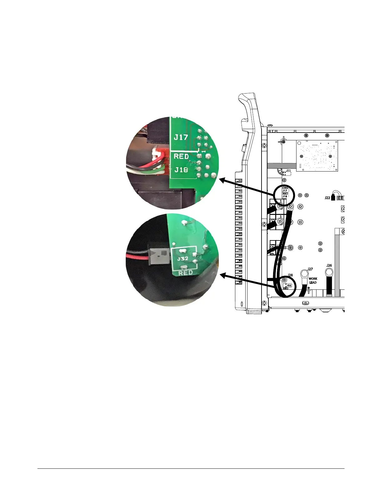
2. From the power PCB side, do the following:
a. Connect the 4-pin connector to the power PCB at J18.
b. Connect the 2-pin connector to the power PCB at J32.
c. For the 2-pin and 4-pin connectors, make sure that the red wire aligns with RED on the
power PCB.
3. Install the fan shroud on the fan.
J22
J27
WORK
LEAD
J26
RED
J18
ORG
J17
J32
J11
B
R
J28
RED
Red wire = top pin
Red wire = bottom pin

 Loading...