EasyManuals Logo
Home>Hypertherm>Welding System>powermax65

Hypertherm powermax65 Field Service Bulletin

Hypertherm powermax65
40 pages
To Next Page IconTo Next Page
To Previous Page IconTo Previous Page
Page #20 background imageLoading...
Page #20 background image
Machine Interface Receptacle with Voltage Divider PCB
20 806980 Field Service Bulletin Powermax65/85/105/125, Powermax65/85/105 SYNC
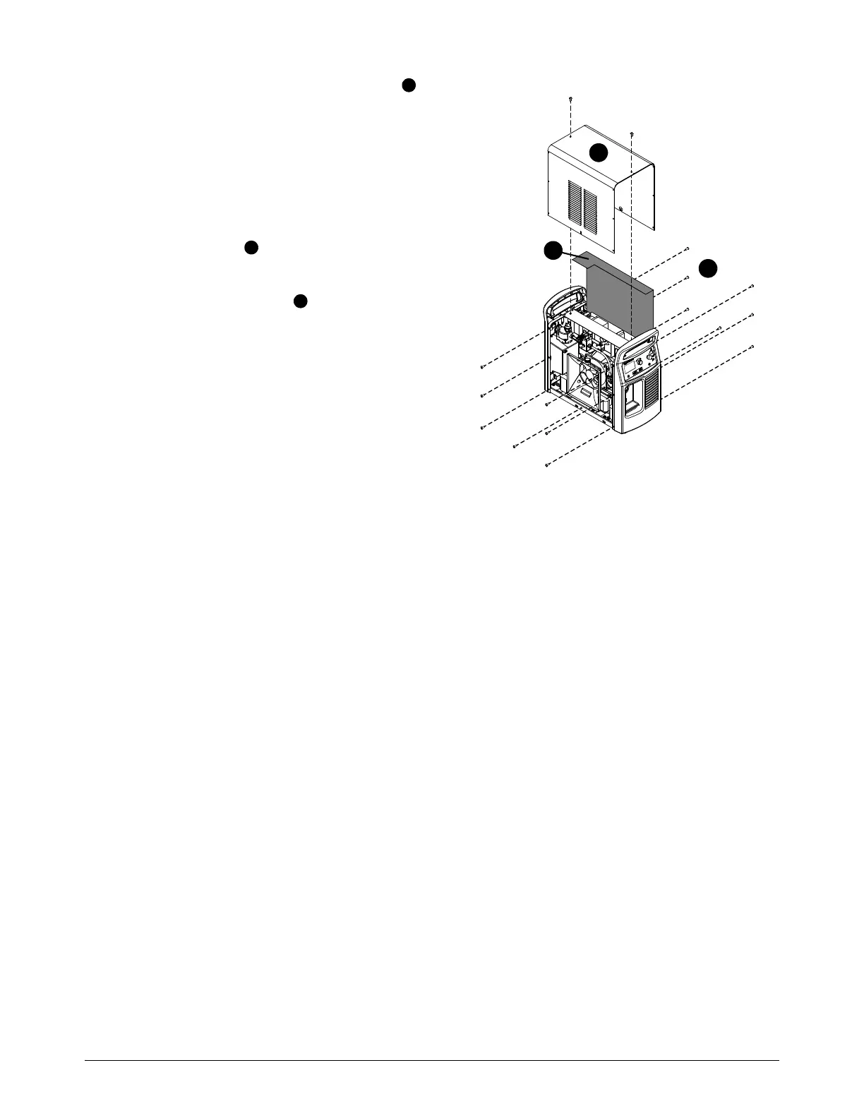
3. Fold the top of the component barrier onto
the top edge of the power PCB, inside the
plasma power supply frame and under the
end panel bracket.
4. Make sure that all of the wires that are
connected to the power PCB are behind the
component barrier.
5. Put the cover on the plasma power supply.
Do not pinch any wires.
6. Install the 16 screws on the plasma power
supply cover. Tighten the screws to 1.7 N·m
(15 lbf·in).
3
4
5
3
4
5

Table of Contents

Other manuals for Hypertherm powermax65

Questions and Answers:

Question and Answer IconNeed help?

Do you have a question about the Hypertherm powermax65 and is the answer not in the manual?

Hypertherm powermax65 Specifications

General IconGeneral
BrandHypertherm
Modelpowermax65
CategoryWelding System
LanguageEnglish

Related product manuals