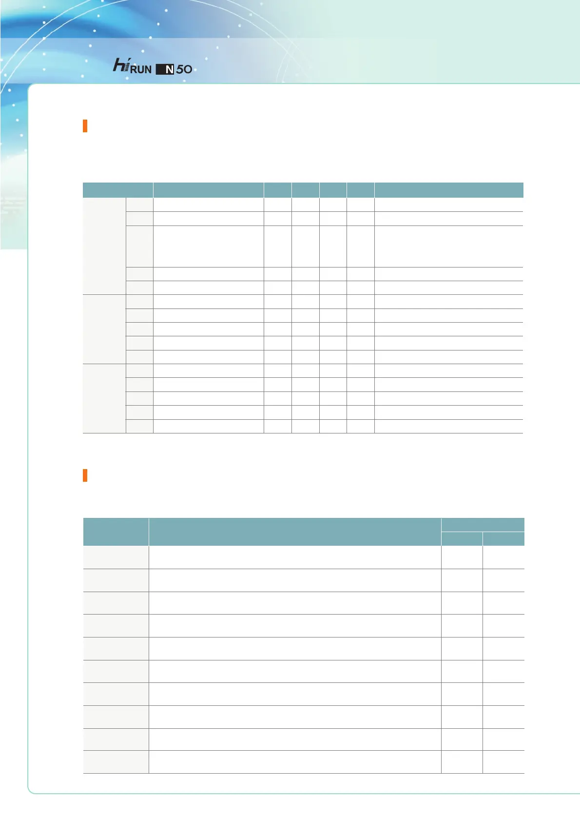
Function List
Protective Functions
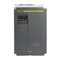
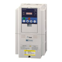
HYUNDAI INVERTER
Expanded Function H Mode
Motor poles
Motor rated current
Primary resistance R1
Secondary resistance R2
Primary inductance Ls
Transient inductance Lsig
No-load current Io
Primary resistance R1
Secondary resistance R2
Primary inductance Ls
Transient inductance Lsig
No-load current Io
Auto-tuning setting
Motor data setting (standard/auto-tuning)
Motor capacity
H01
H02
H03
H04
H05
H06
H07
H08
H09
H10
H11
H12
H13
H14
H15
0
0
0
0
1
1
-
-
11
3-
4
-
-
-
-
-
-
-
-
-
-
-
2
0.1
0.001
0.001
0.1
0.01
0.1
0.001
0.001
0.1
0.01
0.1
8
100.0
30.00
20.00
2000.0
100.0
100.0
30.00
20.00
2000.0
100.0
100.0
-
A
Ω
Ω
mH
mH
A
Ω
Ω
mH
mH
A
2/4/6/8
Motor rated current
setting range: 0.001~30.00 Ω
setting range: 0.001~20.00 Ω
setting range: 0.1~2000.0 mH
setting range: 0.01~100.0 mH
setting range: 0.1~100.0 A
setting range: 0.001~30.00 Ω
setting range: 0.001~20.00 Ω
setting range: 0.1~2000.0 mH
setting range: 0.01~100.0 mH
setting range: 0.1~100.0 A
O: auto-tuning OFF, 1: auto-tuning ON
0: standard motor constant, 1: auto-tuning data
1: 0.75 kW
2: 1.5 kW
3: 2.2 kW
Sensorless
vector
control
Motor
constant
Auto-
tuning
motor
constant
Function code
Name
Initial value
Minimum value
Maximum value
Unit
Code description
Various functions are provided for the protection of the inverter and motor, they also perform the protection function when the inverter breaks down.
Overcurrent
protection
Overload protection
(electronic thermal)
regenerative
Overvoltage
protection
Communication
error
Undervoltage
protection
Output
short-circuit
USP error
EEPROM error
External trip
Temperature trip
Function
Display
Standard operator
Remote operator
Description
When the inverter output current exceeds the rated current by more than approximately 200% while the
motor is locked or reduced in speed,the protection circuit activates, halting inverter output.
When the inverter output current causes the motor to overload, the electronic
thermal trip in the inverter cuts off the inverter output.
If regenerative energy from the motor or the main power supply voltage is high, the protective circuit
activates to cut off the inverter output when the voltage of DC link exceeds the specification.
The inverter output is cut off when communication to the inverter has an error
due to external noise, excessive temperature rise, or other factors.
The inverter output is short-circuited. This condition causes excessive current
for the inverter, so the inverter output is turned off.
The USP error is indicated when the power is turned on with the inverter in RUN state.
(Enabled when the USP function is selected.)
The inverter output is cut off when the EEPROM in the inverter has an error due to
external noise, excessive temperature rise, or other factors.
When the external equipment or unit has an error, the inverter receives the
corresponding signal and cuts off the output.
When the temperature in the main circuit increases due to cooling fan failure,
the inverter output is cut off (only for the model with a cooling fan).
When the input voltage to the inverter decreases, the control circuit does not function normally.
When the input voltage is below the specification, the inverter output is cut off.
E04
E05
E07
E60
E09
E34
E13
E08
E12
E21
Over.C
Over.L
Over.V
Com.ERR
Under.V
PM.ERR
USP
EEPROM
EXTERNAL
OH.FIN
 Loading...