INSTALLATION AND OPERATION INSTRUCTIONS
14
IBC INDIRECT WATER HEATERS - ALL MODELS
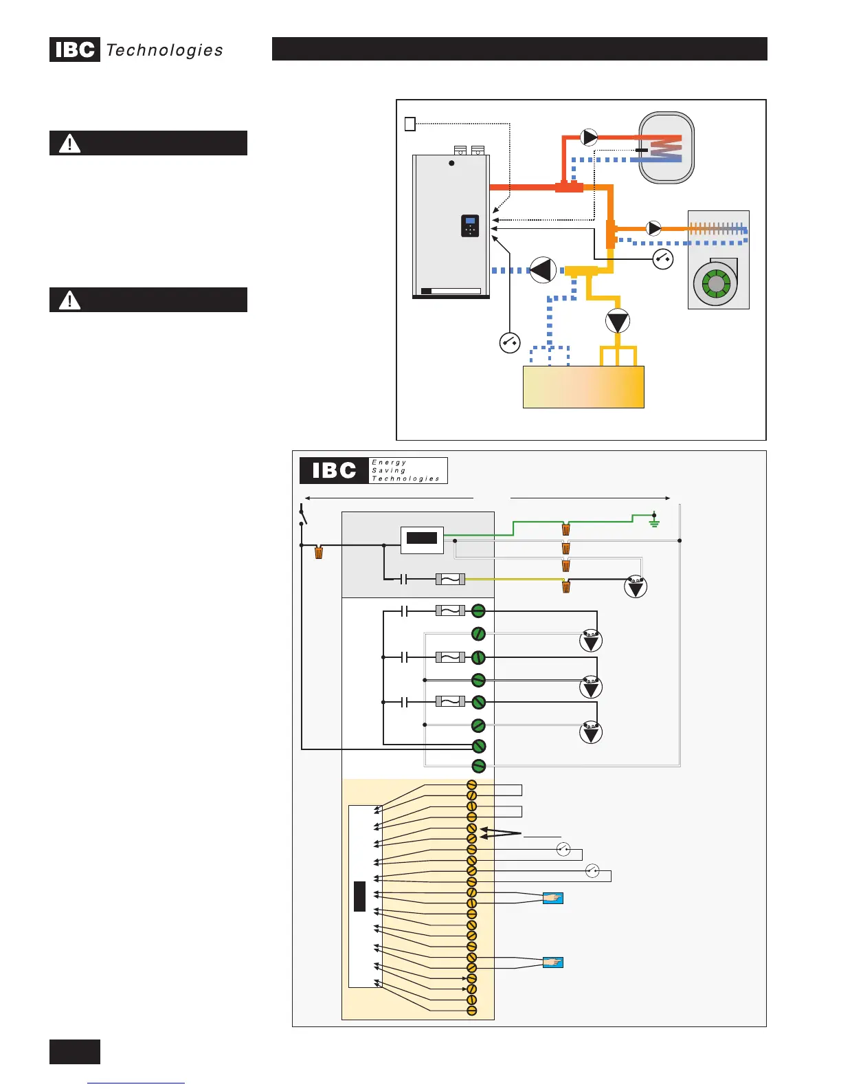
8) - Schematics
LOW TEMP RADIANT
3 Load Primary / Secondary Piping/w Pumps
IBC
BOILER
IBC
DHW
FAN COIL
Boiler Pump
(P1)
Domestic Hot Water Sensor
DHW Pump
(P2)
Fan Coil
Pump
(P3)
Radiant
Pump
(P4)
Outdoor Sensor
Fan Coil
Thermostat
Radiant
Thermostat
Mechanical
Drawing #1
ELECTRICAL LADDER DIAGRAM
3 Load Primary/Secondary with Pumps - Refer to Mechanical Drawing #1
Valid for all IBC Boilers except the SL 80-399 - refer to SL 80-399 I&O Manual
IBC
CB
Input to ProcessorInput to Processor
DO NOT connect ANYTHING to these terminals
Auxiliary Interlock
Fan Coil Thermostat
Radiant Thermostat
Interlock 1
Therm. 1
Interlock 2
Therm. 2
Therm. 3
Outdoor S.
Indoor S.
2nd Loop S.
DHW S.
Boiler Net +
Ext. Cont. –
G
120VacL N
IBC Control Board
Boiler Pump
(P1)
CB-1
Yellow
White
CB-2
CB-3
CB-4
P/ V Power - L
P/ V Power - N
P/ V3 - N
P/ V3 - L
P/ V1 - N
P/ V1 - L
P/ V2 - N
P/ V2 - L
IBC
CB
Domestic Hot Water Sensor
Supplied with IBC Water Heater
Interlock 1
Interlock 2
Therm. 1
Therm. 2
Therm. 3
Outdoor S.
Indoor S.
2nd Loop S.
DHW S.
Boiler Net –
Ext. Cont. +
White
Green
Black
Fuse - 5A
Fuse - 5A
Fuse - 5A
Fuse - 5A
G1
DHW
Pump
(P2)
Fan Coil
Pump
(P3)
Radiant
Pump
(P4)
G2
G3
G4
G5
G6
G7
G8
O1
O2
O3
O4
O5
O6
O7
O8
O9
O10
O11
O12
O13
O14
O15
O16
O17
O18
O19
O20
O21
O22
Auxiliary Interlock
Outdoor Sensor
Supplied with IBC Boiler
NOTE
When using the sequential
load feature of the IBC boiler,
attention must be paid to
the operation of system
components in order to
ensure they are compatible.
Many air handlers (fan
coils) for instance have a
thermostat connection that
will energize an internal relay
to operate the air handler
circulator and its fan on
a call for heat. This may
result in operation of these
components when other
loads are running at a higher
priority, resulting in cold air
blowing, or robbing heat from
another load.
Some wiring alteration may
be required to divorce both
of these functions from
thermostat control in favour
of more effective control from
the IBC boiler.
NOTE
Full sized and more detailed
application drawings can be
downloaded from our web
site.
www.ibcboiler.com
 Loading...