17
INSTALLATION AND OPERATION INSTRUCTIONS
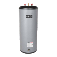
IBC INDIRECT WATER HEATERS - ALL MODELS
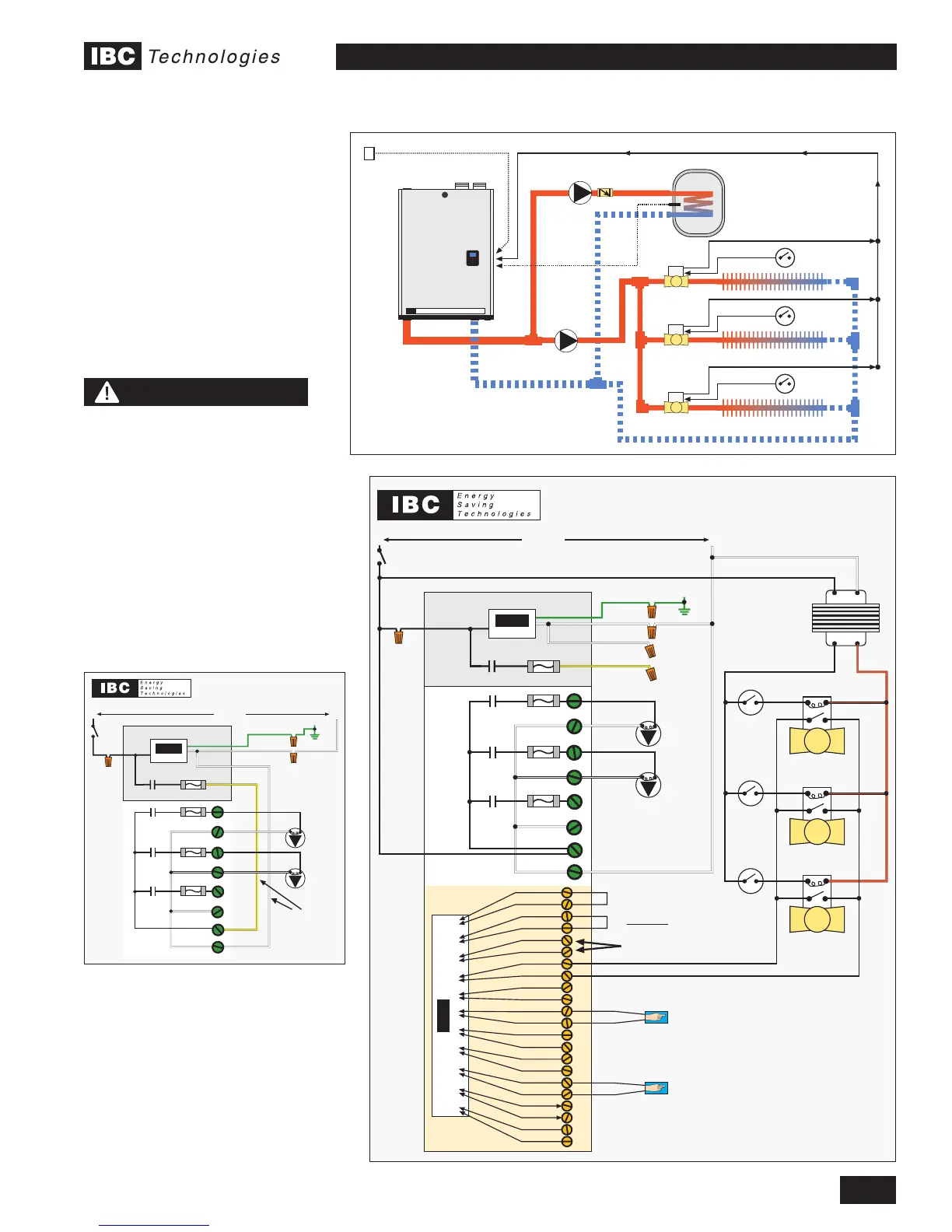
ELECTRICAL LADDER DIAGRAM
“Hybrid” Zoning System - 2 Temp Parallel Piping/w DHW Pump and
Baseboard System Zone Valves - Refer to Mechanical Drawing #5
Valid for all IBC Boilers except the SL 80-399 - refer to SL 80-399 I&O Manual
IBC
CB
Input to ProcessorInput to Processor
Interlock 1
Therm. 1
Interlock 2
Therm. 2
Therm. 3
Outdoor S.
Indoor S.
2nd Loop S.
DHW S.
Boiler Net +
Ext. Cont. –
G
120VacL N
IBC Control Board
CB-1
Yellow
White
CB-2
CB-3
CB-4
P/ V Power - L
P/ V Power - N
P/ V3 - N
P/ V3 - L
P/ V1 - N
P/ V1 - L
P/ V2 - N
P/ V2 - L
IBC
CB
Domestic Hot Water Sensor
Supplied with IBC Water Heater
Interlock 1
Interlock 2
Therm. 1
Therm. 2
Therm. 3
Outdoor S.
Indoor S.
2nd Loop S.
DHW S.
Boiler Net –
Ext. Cont. +
White
Green
Black
Fuse - 5A
Fuse - 5A
Fuse - 5A
Fuse - 5A
G1
DHW
Pump
(P1)
Baseboard
Pump
(P2)
G2
G3
G4
G5
G6
G7
G8
O1
O2
O3
O4
O5
O6
O7
O8
O9
O10
O11
O12
O13
O14
O15
O16
O17
O18
O19
O20
O21
O22
Outdoor Sensor
Supplied with IBC Boiler
DO NOT connect
ANYTHING
to these terminals
Transformer
120 Vac
24 Vac
R
C
N
L
(ZV1)
(ZV2)
(ZV3)
BB Zone 1
Thermostat
BB Zone 2
Thermostat
BB Zone 3
Thermostat
DHW
DHW Pump
(P1)
Baseboard
Pump
(P2)
Outdoor Sensor
Ganged end-switch dry contact closure
IBC
BOILER
IBC
“Hybrid” Zoning System
2 Temp Parallel Piping/w DHW Pump
and Baseboard system Zone Valves
Domestic Hot
Water Sensor
BB Zone 1
Thermostat
Mechanical
Drawing #5
BB Zone 1
Valve (ZV1)
BB Zone 2
Valve (ZV2)
BB Zone 3
Valve (ZV3)
Zone Val ve end-switch
BB Zone 1
Thermostat
Zone Val ve end-switch
BB Zone 1
Thermostat
Zone Val ve end-switch
ZV
ZV
ZV
NOTE
IBC VFC Series boilers
have been designed to take
advantages of the many
benets of primary/secondary
piping. These models have a
software routine that utilizes
the boiler pump contacts on
start-up in order to prove
ow. The sketch below details
a wiring modication that
must be made when using
parallel pumping with IBC
VFC model Boilers.
ELECTRICAL LADDER DIAGRAM DETAIL
VFC Series Boiler Wiring for Parallel Piping
Valid for IBC VFC 15-150 and VFC 45-225 Model Boilers
G
120Vac
IBC Control Board
CB-1
Yellow
White
CB-2
CB-3
CB-4
P/ V Power - L
P/ V Power - N
P/ V3 - N
P/ V3 - L
P/ V1 - N
P/ V1 - L
P/ V2 - N
P/ V2 - L
IBC
CB
White
Green
Black
Fuse - 5A
Fuse - 5A
Fuse - 5A
Fuse - 5A
G1
DHW
Pump
(P1)
Heating
Pump
(P2)
G2
G3
G4
G5
G6
G7
G8
Connect Yellow and
White Primary Pump
wires to the bottom
two terminals on the
Green Terminal Strip
On a VFC Model boiler, locate the
Yellow and White pair of wires in the
wiring box behind the IBC Control.
Connect the Yellow wire to the “P/V
Power L” terminal second from the
bottom on the Green terminal plug.
Connect the White wire to the bottom
terminal labelled “P/V Power N”. This
will satisfy the boiler’s ow proving
routine when either zone starts up.
 Loading...