INSTALLATION AND OPERATION INSTRUCTIONS
3-2
DC SERIES BOILERS / WATER HEATERS DC 15-95, DC 15-96, DC 20-125, DC 33-160
3.2 PRIOR TO START-UP
3.2.1 Pre-Ignition Checks
1. Fill condensation trap. Ensure venting system is complete and seal tested.
Conrm any common venting system at the installation site is isolated and
independent of the DC boiler / water heater, that any holes left from removal
of a previous boiler have been sealed, and that any resizing of the old ue
has been done.
2.
Check water piping system is fully ushed and charged, and that all air has
been discharged through loosened bleed caps. Use a minimum water pressure
of 12 psig and conrm pressure relief valve is installed and safely drained.
3. Check to see that adequate gas pressure is present at the inlet gas supply
test port. With the boiler / water heater gas valve shut off, open the test port
(using a small (1/8" or 3 mm) at screwdriver, open the test port by turning its
center-screw 1 full turn counterclockwise. Connect a manometer and open
the gas control valve. Requirements are minimum 5" w.c and maximum 14"
w.c. Check to ensure no gas leaks.
4. Perform a nal check of electrical wiring and provide power to the boiler /
water heater to initialize operation.
3.2.2 Test Ignition Safety Shutoff
With the boiler / water heater in operation, test the ignition system safety shutoff
device by shutting the manual gas valve immediately outside the boiler / water
heater case. Ensure boiler / water heater has shut off and the appropriate Error
information is displayed on the Main Display screen. To restart boiler, reset power.
COMMISSIONING
The DC Series modulating boilers / water heaters are factory calibrated to operate
with natural gas at sea level. The Low Fire (Zero Offset) screw is not to be
adjusted in the eld. The High re (Gas : Air Ratio Adjustment) screw may have
to be adjusted to attain optimum combustion results if required, however, no
mixture adjustment shall be performed unless done by a qualied technician
using properly functioning and calibrated combustion analyzing equipment.
This boiler / water heater model can burn either Natural gas or Propane if
equipped with the correct specied orice. Examine the rating plate of the
boiler / water heater to ensure it is congured for the fuel you are using. If
the boiler / water heater is to be converted from Natural Gas to Propane or
from Propane to Natural Gas a Fuel Conversion Kit must be installed. The
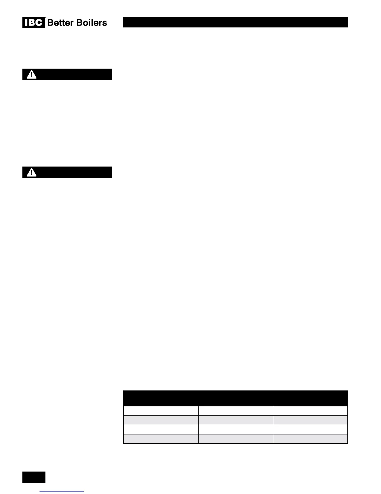
correct Fuel Conversion Kit part number can be found in Table 10.
MODEL NUMBER NATURAL GAS
TO PROPANE
PROPANE TO
NATURAL GAS
DC 15-95 P-747 P-748
DC 15-96 P-747 P-748
DC 20-125 P-737 P-738
DC 33-160 P-702 P-703
Table 10: Fuel Conversion Kits
3.3
DANGER
Making adjustments to
the IBC gas valve without
a properly calibrated gas
combustion analyzer and by
persons who are not trained
and experienced in its use
is forbidden. Failure to use
an analyzer can result in an
immediate hazard.
DANGER
Fill trap with water before
boiler / water heater is rst
red to prevent exhaust
fumes from entering room.
Never operate the boiler /
water heater unless the trap is
lled with water.
Failure to comply will result
in severe personal injury or
death.
 Loading...


