7.3.2 Replacing the gas valve in EX 700 and EX 850 models
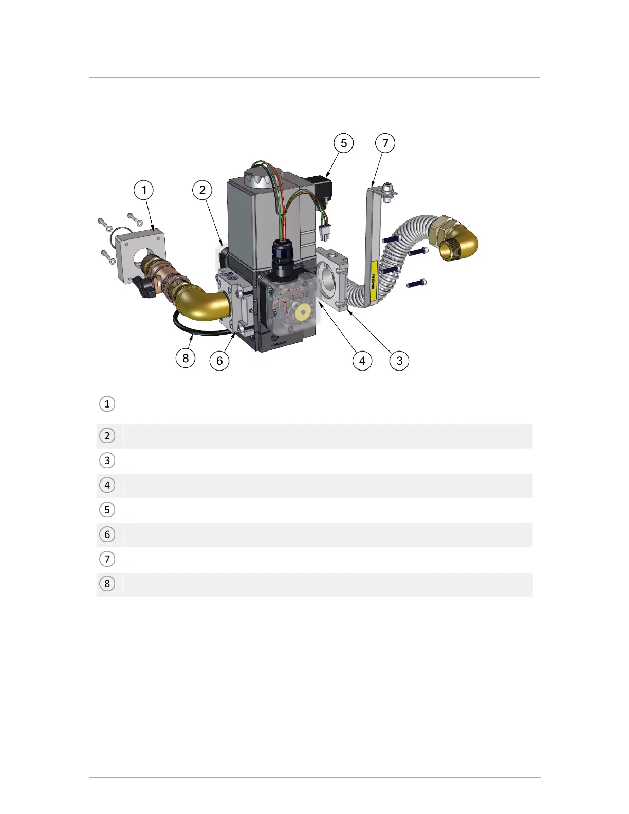
Four (4) bolts connecting gas valve and mixing device. Keep gasket and bolts for re-
assembly.
Location of high gas pressure switch.
Gas valve inlet: Four (4) bolts of the flange. Keep gasket and bolts for re-assembly.
Low gas pressure switch.
Gas valve electrical connector
Gas valve outlet: Four (4) bolts of the flange. Keep gasket and bolts for re-assembly.
Supporting bracket for gas valve
Black tubing
Figure 71 Accessing the gas valve - EX 700, 850
1. Turn off the electric power and gas supply to the boiler.
2. Ensure that the boiler cools down to the surrounding temperature. Do not drain the boiler
unless freezing conditions are expected during this procedure.
Section: Service and maintenance
 Loading...