4-5
MAINTENANCE
VFC 15-150, VFC 45-225 MODULATING GAS BOILERS
4.2.5 Water Pressure Sensor
TYPE: Water Pressure (IBC # 240-006)
FUNCTION: water pressure and ow sensing.
INSTALLATION: (see Diagram 6.1-1, and Diagram 6.1-2).
4.2.6 High Limit
PART#/TYPE: IBC # 240-032 High Limit calibrated for 200°F, 15°F differential.
FUNCTION: Shuts boiler off when water temperature exceeds safety limit.
INSTALLATION: (see Diagram 6.1-1 for correct position). Mount with Honeywell
Tradeline #107408 Heat Conductive Compound between the base of the hi-limit
switch and the mounting surface.
4.2.7 Transformer
PART#/TYPE: IBC # 240-008 Primary- 120 VAC; Sec.- 24 V AC; 40VA control
transformer.
FUNCTION: Provides 24 VAC for the control board, for (1) the control / safety
circuit, (2) relays for pump and zone valve control, plus (3) input to DC power
converters for 5 V and 12 V circuits (NB not for use to power external zone
valves).
INSTALLATION: (see Diagram 6.1-1 for correct position).
4.2.8 Temperature Sensors
PART#/TYPE: IBC # 240-006 Thermistor; 10,000Ω with Beta = 3892
FUNCTION: Senses water temperature. Signals controller to adjust output
according to water temperature.
INSTALLATION: (see Diagram 6.1-1 for correct position).
4.2.9 Control Module
PART#/TYPE: IBC # 500-0044 Touch Screen boiler controller, V10.0
FUNCTION: (see Touch Screen Boiler Controller Manual for an explanation of
controller function).
INSTALLATION: (see Diagram 6.1-1 for correct position). The 4 screws on
the front panel corners secure the cover. To remove the unit from the mounting
brackets, ensure all wires are removed from the connectors on the edge and back
of the control module. Place ngers on the board edge only when handling.
There is a 3V lithium battery (IBC # 240-024) for powering the permanent memory
if AC power is not connected.
On-board eld replaceable fuses (IBC # 240-023) are 5A, slow blow, 5mm x
20mm, and must be replaced using these same specs.
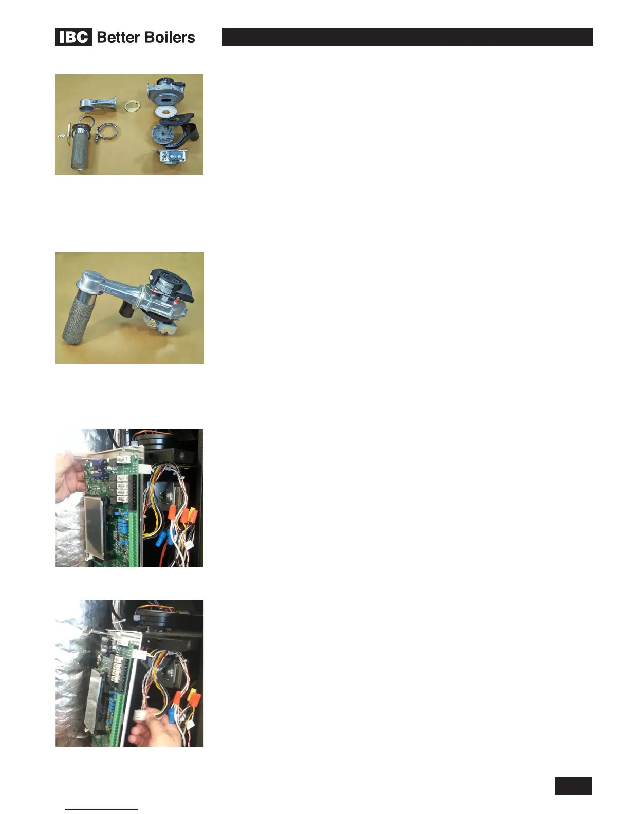
Main combustion components
(clockwise from left) Burner, with
ignitor and V clamp - Fan coupler
- Fan/Blower - Mixing plates &
housing - Gas valve
Combustion group assembly
Control Module removal
Disconnecting Control Module plugs
 Loading...


