INSTALLATION AND OPERATION INSTRUCTIONS
6-6
VFC 15-150, VFC 45-225 MODULATING GAS BOILERS
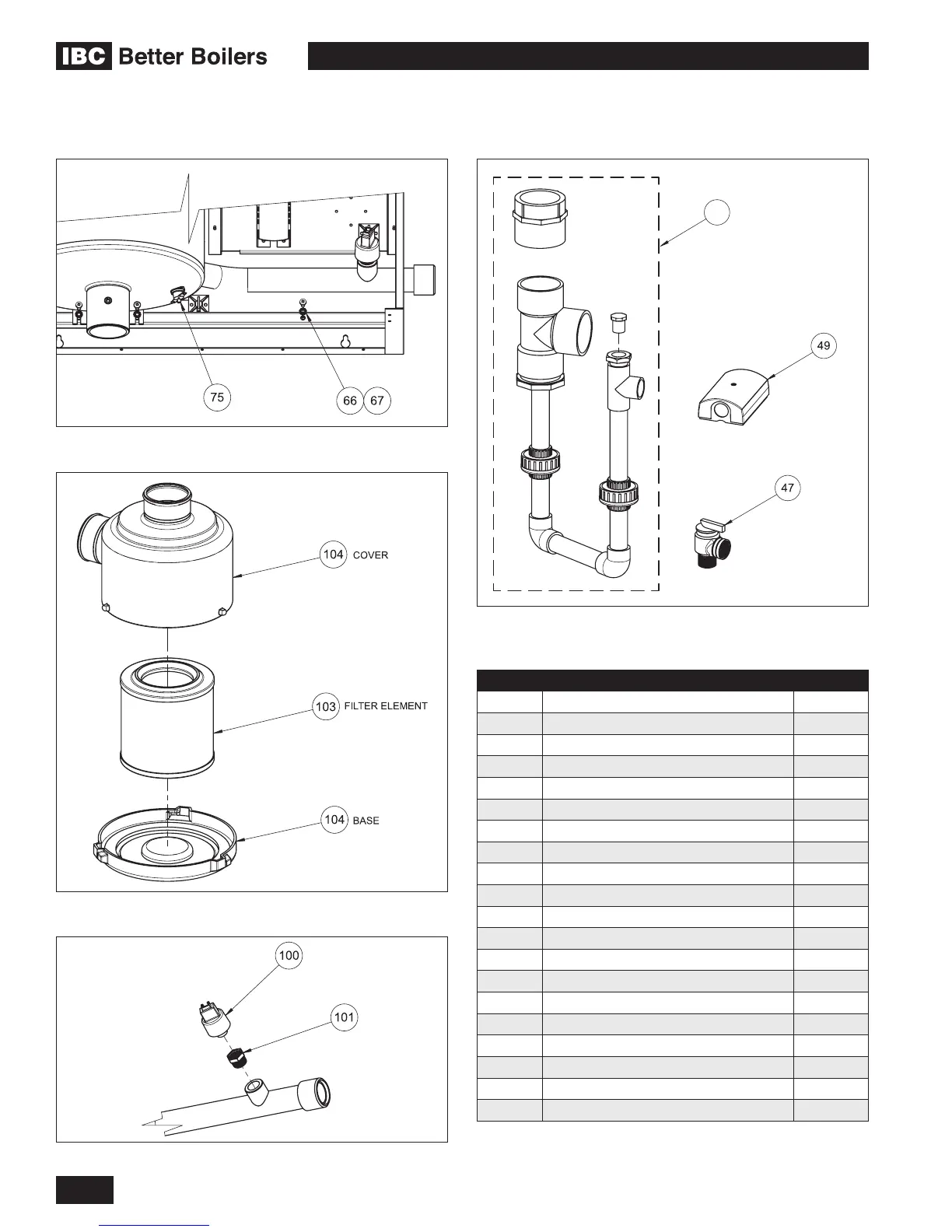
Diagram 6.3-3: Water pressure sensor group
Diagram 6.3-1: Vent high limit
Diagram 6.3-4: Accessory parts kit (shipped with boiler)
51 TRAP/EXHAUST KIT
Diagram 6.3-2: Intake Air Filter (order separately)
ITEM # DESCRIPTION PART #
47 Pressure Relief Valve 180-005
49 Outdoor Temperature Sensor 240-025
51(a) Trap/Exhaust Kit VFC15-150 P-150
51(b) Trap/Exhaust Kit VFC45-225 P-151
66 Washer, #10, External Tooth 150-085
67 Screw, #10-32 x 1/2" 150-084
75 Switch, Snap disk, Manual Reset, 230F 240-030
100 Sensor, Water Pressure 240-006
101 Pressure Sensor Bushing 250-023
103 Intake Air Filter Element 180-103
104 Intake Air Filter Housing 180-104
PARTS BELOW - NOT SHOWN
68 Ignition Cable 210-001
69 Fuse Kit (10 pack) P-114
71 8 Position Terminal Block - Green 240-019
72 22 Position Terminal Block - Orange 240-020
73 DC to AC Fan Harness Conversion Kit 71-ACDC
74 Acid Neutralization Tank 180-029
102 Ignitor Kit w/Gasket P-142
6.3 ADDITIONAL PARTS DIAGRAMS
 Loading...


