1-1
INSTALLATION
VFC 15-150, VFC 45-225 MODULATING GAS BOILERS
INSTALLATION1.0
GENERAL
VFC gas-red modulating boilers are low pressure, fully condensing units having
variable input ranges (a) 15 MBH (15,000 Btu/hr) to 150 MBH (15-150 model,
0 to 12,000’) and (b) 45 MBH to 225 MBH (45-225 model, 0 to 12,000’). The
boilers are approved as “Category IV” vented appliances using either Direct
Vent (sealed combustion) or indoor combustion air, providing a great degree of
installation exibility.
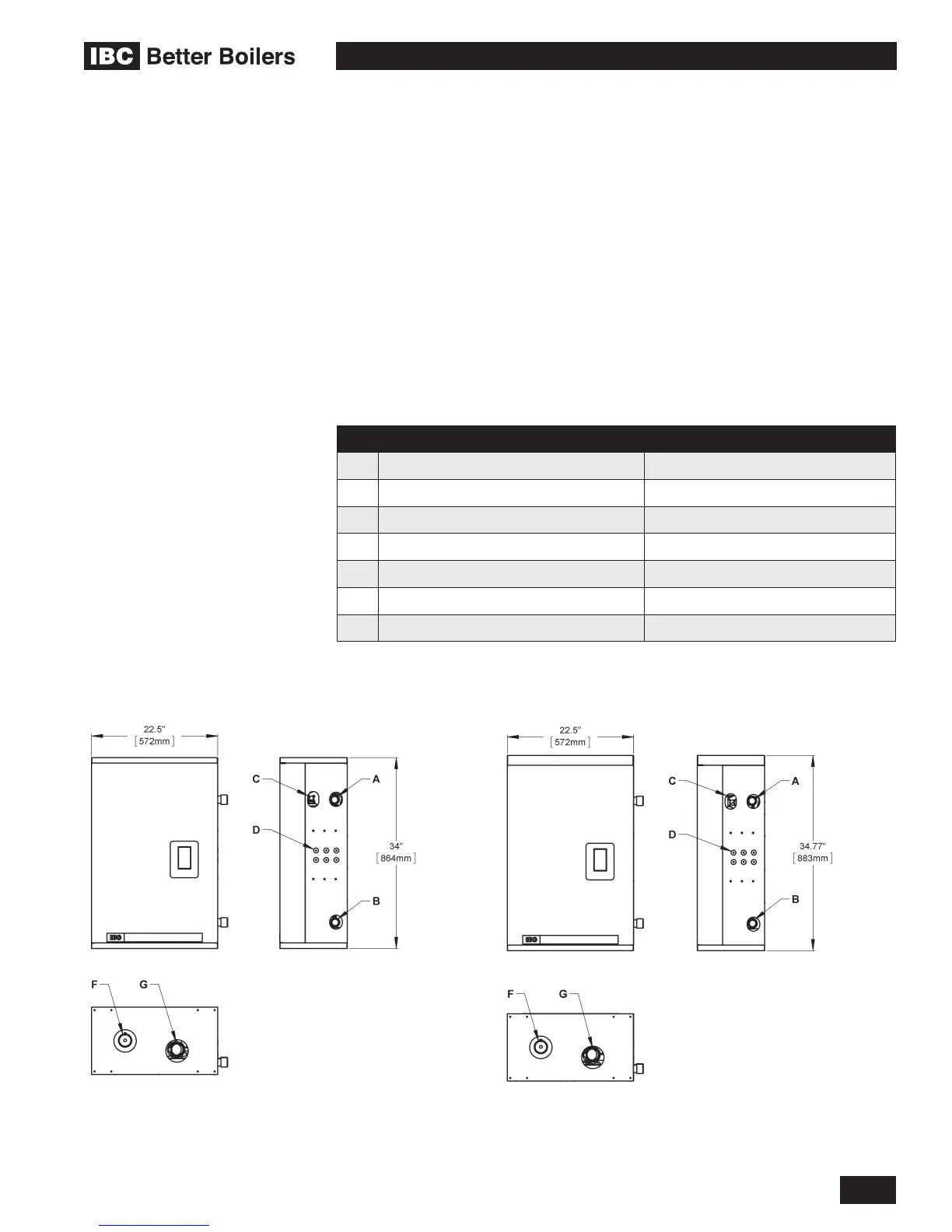
Figure 1 shows outer case dimensions and piping and electrical holes. Use this
diagram to nd a suitable location for the boiler. See also Section 1.3 Location.
DESCRIPTION SIZE
A Water Outlet 1-1/4" NPT-M
B Water Inlet 1-1/4" NPT-M
C Gas Inlet 1/2" NPT-F
D Knock-outs (6) 1/2"
E Touch Screen Display 2-1/4” x 4”
F Exhaust Vent 4.0" Hole
G Combustion Air 4.0" Hole
Table 1: Connections
1.1
Figure 1a: Dimensions / Connections for VFC 15-150 Figure 1b: Dimensions / Connections for VFC 45-225
 Loading...


