Check the operation of the sensor by isolating the boiler from its system piping, and close the system
fill valve, and then crack the pressure relief valve. The pressure displayed should reflect declining
pressure. If it remains “fixed”, drain the boiler and replace the sensor, or dislodge any blocking debris
from the sensor inlet channel and reinsert.
8.1.4 Safety and Ignition Module (SIM+)
The SIM+ is a safety control, certified to conform to the UL 60730-5-5 and ANSI Z21.20-2014 •
CAN/CSA-C22.2 No. 60730-2-5-14 standards.
The module controls the boiler’s combustion fan, gas valve, sensors, safety and ignition functions
including:
Direct spark automatic ignition
Flame detection and current measurement
Supply water temperature sensing
Flue gas temperature sensing
Supply water maximum temperature shutdown
Flue gas maximum temperature shutdown
Low water cut-off.
The SIM+ continuously communicates with the boiler’s main controller reporting sensor readings and
status. The sensor readings and error status, if any are displayed on the boiler controller’s screen.
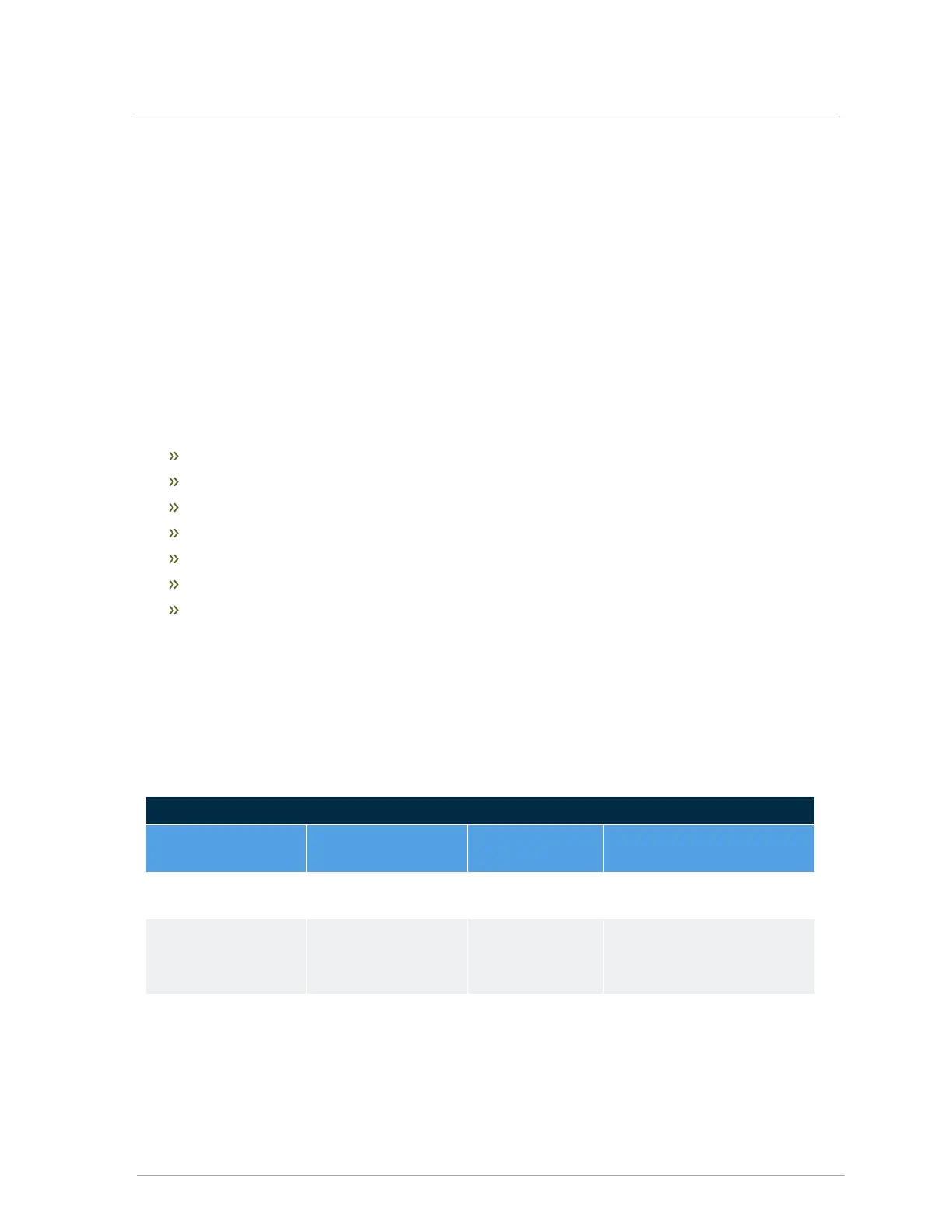
8.1.4.1 Table showing LED operating status
Its two status LEDs indicate the operating status as shown in the table below.
SIM Status Indicators
LED 1 LED 2 State
Description, LED status
indication
Rapid flash Power up or
resetting
startup checks and
initialization
Off Off Standby
LED 1 Off=flame or sparking
LED 2 = Burner-on call state
Off On Pre-purge or inter-
purge
LED 1 Off=no flame or
sparking
LED 2 = Burner-on call state
8.1.4 Safety and Ignition Module (SIM+)
 Loading...