Item Description
E/G E X brace
G M10 x 25 Hex bolt, X brace
J/H J Air flow plate
H M6 x 16 Flat head screw, Air flow plate
I Ruggedized latch kit
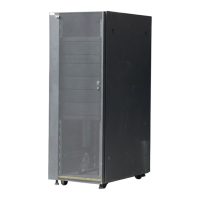
Figure 86. 7965-S42 rack ruggedized kit parts
To remove the X brace, perform the following tasks:
1. Remove the eleven M10 x 25 (G) X brace bolts.
2. Swing the brace (E) out of the rack.
3. Lift up the brace until the hinge pins clear the barrel of brace hinge brackets (A and B).
4. Remove the brace.
To install the X brace, perform the following tasks:
1. Lift the brace and place the hinge pins in the barrel of the brace hinge bracket (A and B).
2. Swing the brace (E) into the rack.
3. Install the eleven M10 x 25 X brace bolts and torque them to 19 ± 2 Nm (14 ± 1.5 ft lb).
Earth (ground) bonding the rack
Electrical bonding is the practice of intentionally electrically connecting all exposed metallic non-current-
carrying items in a room or building as protection from electric shock. The following sections provide
instructions for earth (ground) bonding the rack side covers and the front and rear doors to the rack
frame.
Rack frame connection points
Two connection points are available on the rack frame.
About this task
These connection points are identied by the international earth (ground) symbol.
The following gure shows the ground points on the rack frame.
124
Power Systems: Racks and rack features

 Loading...