Do you have a question about the IBM Personal System/2 65 SX and is the answer not in the manual?
| Manufacturer | IBM |
|---|---|
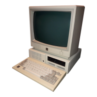
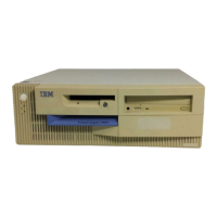
| Model | Personal System/2 65 SX |
| Category | Desktop |
| CPU | Intel 80386SX |
| CPU Speed | 16 MHz |
| Floppy Drive | 3.5" 1.44 MB |
| Graphics | VGA |
| Operating System | PC DOS |
| Ports | Serial, Parallel, Keyboard, Mouse |
| Expansion Slots | Micro Channel Architecture (MCA) slots |
| Storage | 40 MB hard drive (optional) |
Lists system-board devices and features for the Model 65 SX.
Shows the address map for system-board I/O functions.
Details performance and physical specifications of the system.
Explains the power supply requirements and output voltages.
Organizes the I/O address space used by system-board POS.
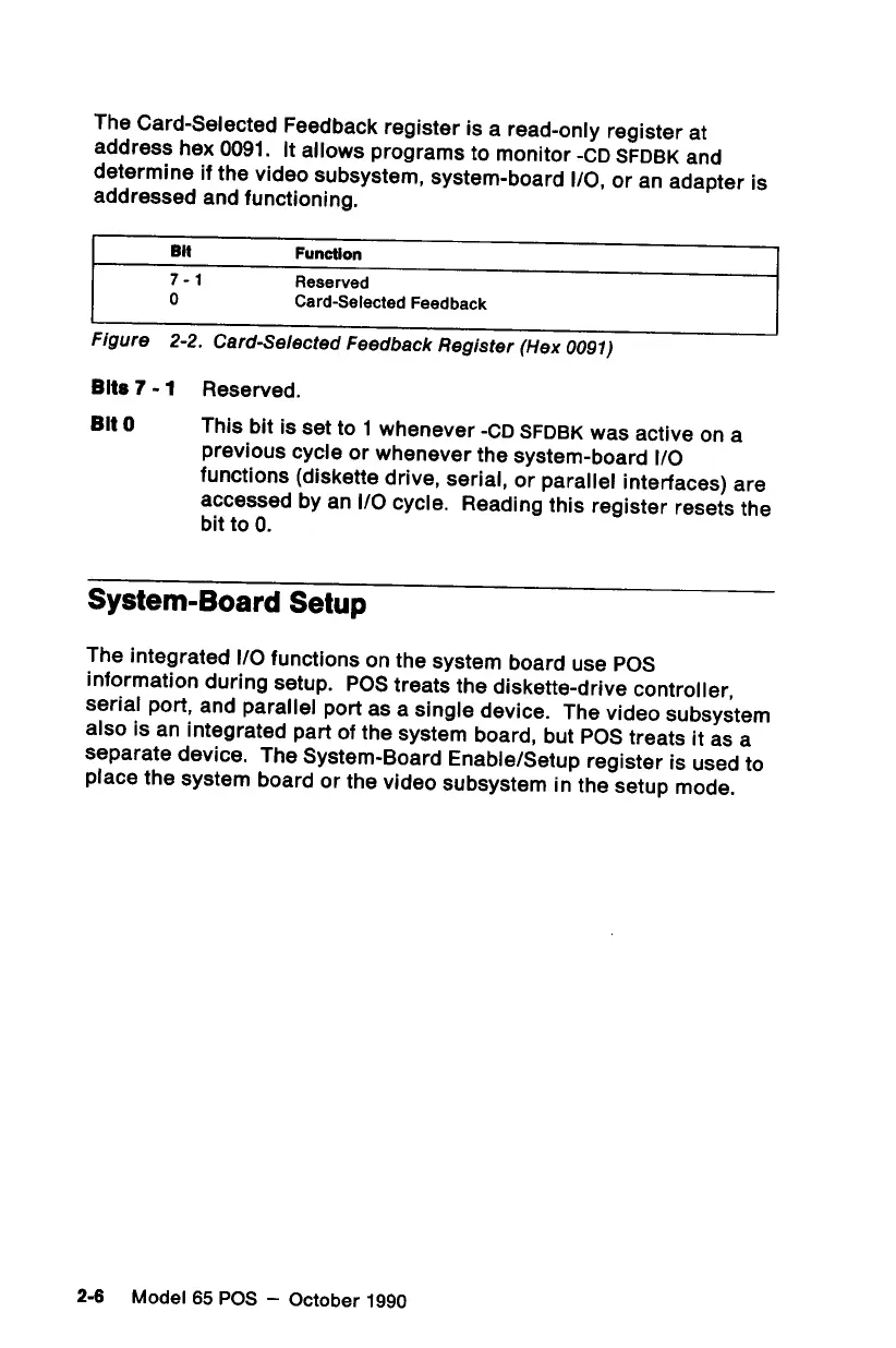
Explains POS information used by the system board for setup.
Controls system-board I/O functions and video subsystem setup.
Details POS registers for memory and configuration.
Selects the channel connector for configuration.
Describes the 80386SX microprocessor and 80387SX math coprocessor.
Details the Micro Channel architecture implementation.
Manages bus access and prioritization for intelligent subsystems.
Information on the Type 1 diskette-drive controller.
Overview of ROM, RAM, and RT/CMOS RAM types.
Details the real-time clock and CMOS RAM chip.
Defines bit definitions and addresses for real-time clock bytes.
Details Status Registers A, B, C, and D.
Shows bit definitions for CMOS RAM configuration bytes.
Covers System-Control Port B (Hex 0061) and Port A (Hex 0092).
Details reserved bytes for the power-on password.
Lists compatible interfaces and components.