4. Locate the disk drive or solid-state drive to be replaced and record the location information. Then,
use the location information to activate the identify light for that drive. For instructions, see “Finding
the location code and activating the indicator light for a part by using the IBM i operating system”
on page 130.
5. Determine whether the disk drive or solid-state drive to be removed is a non-configured drive by
completing the following steps:
a. Type strsst on the command line of the IBM i session, and then press Enter.
b. Type your service tools user ID and service tools password, and then press Enter.
c. Select Work with disk units, and then press Enter.
d. Select Display Disk Configuration, and then press Enter.
e. Select Display non-configured units, and then press Enter.
6. Is the failed drive listed as a non-configured drive in the display?
v No: Continue to “Removing and replacing a disk drive or solid-state drive in the 8284-21A
or 8284-22A system with the power turned on in IBM i” on page 58.
v Yes: Determine if the disk drive to be removed was replaced by a hot spare when it failed. A
xxxx9031 error logged close to the same time of the original disk failure indicates the automatic
Rebuild of the data to a hot-spare device, then go on to the next step.
7. Is the disk drive to be removed controlled by the load source adapter?
v No: Go to step 10.
v Yes: Go to the next step.
8. Is the disk drive to be removed located in a valid load source position?
v No: Go to “Configuring a disk drive or solid-state drive on a load source adapter for hot-spare
protection by using the IBM i operating system” on page 117.
v Yes: Go to step 10.
9. Choose the concurrent maintenance option. This option shows the disk drive location on the
concurrent maintenance display. Go to step 12 on page 74.
10. From the Hardware Service Manager, navigate to Select Device Concurrent Maintenance option.
Press Enter. The Device Concurrent Maintenance display is shown, as shown in the Figure 72 on
page 74.
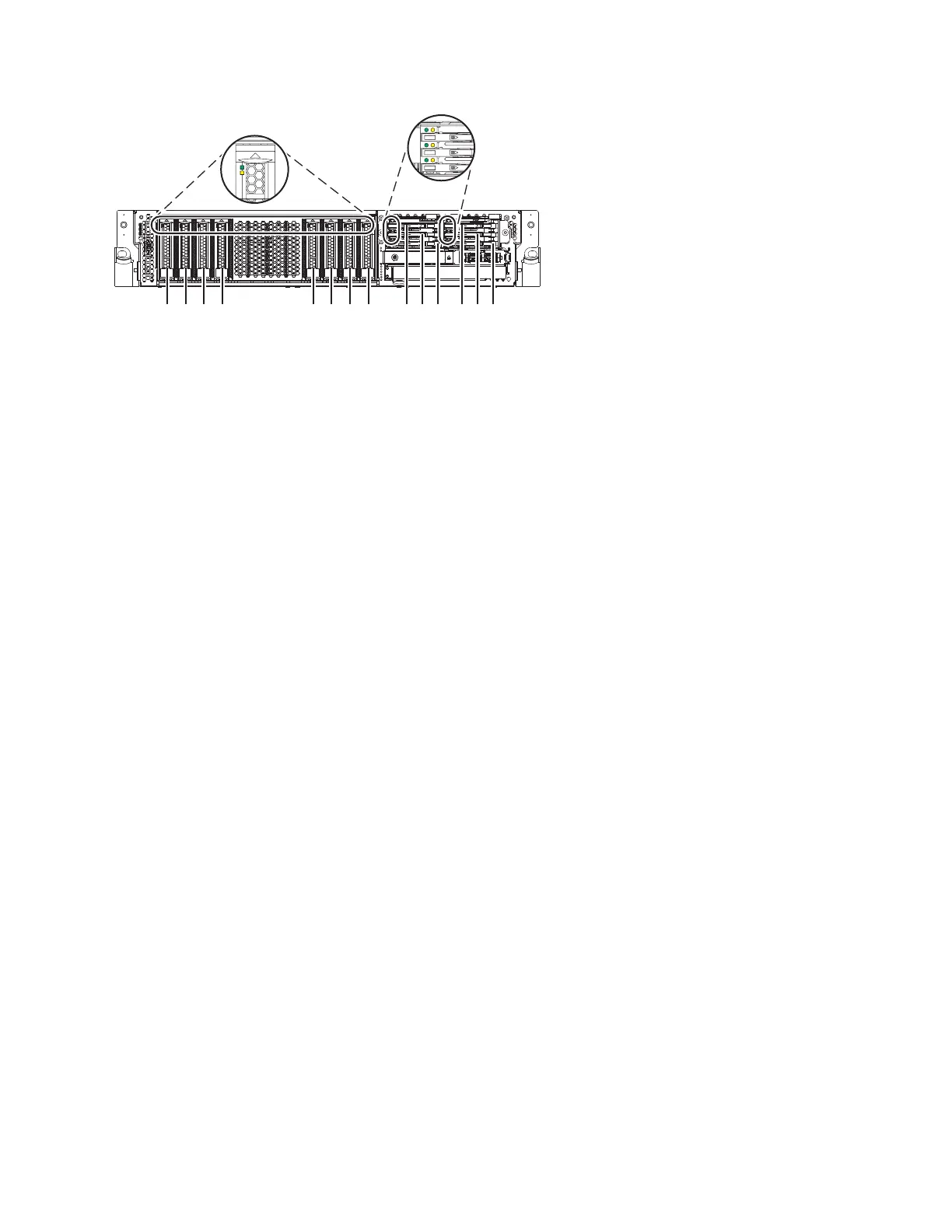
P2-D14
P2-D12
P2-D10
P2-D13
P2-D11
P2-D9
P2-D8
P2-D7
P2-D6
P2-D5
P2-D4
P2-D3
P2-D2
P2-D1
P8HAL509-1
Figure 71. Disk drive, solid-state drive, and service indicator locations for an expanded function system
Disk drives or solid-state drives 73
 Loading...