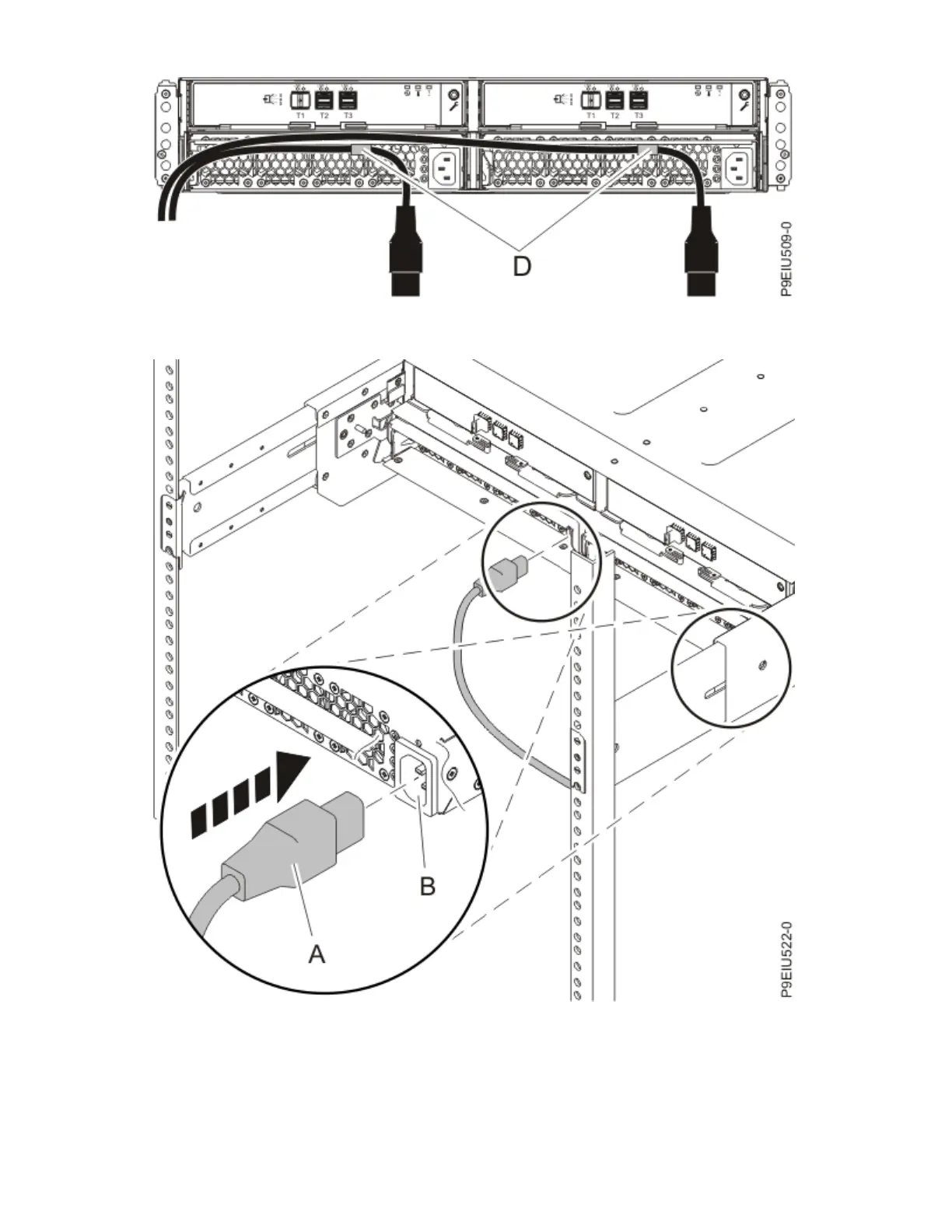
Figure 31. Routing the power cords through the cord retention brackets
4. If necessary, connect the power cords to the left and right power supplies.
Figure 32. Connecting the power cords
5. Reinstall the left cover (A), which contains the service indicators, and the right cover (B).
a. Fit the slot on the top of the cover over the tab on the chassis flange.
b. Rotate the cover down until it snaps into place. Ensure that the inside surface of the cover is flush
with the chassis.
34
Power Systems: Installing the 5887 disk drive enclosure
 Loading...