Procedure
1. Ensure that the system (earth) ground connection has been made. See the “System Grounding” on
page 75.
2. If a filler panel is installed, remove the filler panel from the power supply bay by loosening the captive
screw.
3. Ensure that the power switch is in the off (0) position on the power supply you are installing.
4. Grasp the power supply handle with one hand, place your other hand underneath the power supply,
and slide the power supply into the power supply bay. Ensure that the power supply is fully seated in
the bay.
5. Plug the power cable into the power supply, and place the cable retention device to ensure that the
cable cannot be pulled out.
6. Connect the other end of the power cable to an AC power source.
7. Turn the power switch to the on (|) position on the power supply. Turning the power switch on also
locks the power supply in the bay.
8. Verify power supply operation by checking that the power supply LEDs are in the following states:
• Input OK LED is IN.
• Output Fail LED is Fault.
• ID LED is blue.
Connecting an AC Power Supply to an AC Power Source
Use one power cord to connect a 3-kW power supply to an AC power source and to ground the power
supply. Depending on the software power mode configured on the switch, either connect all of the power
supplies to one AC power source (grid) or half of the power supplies to the first independent AC power
source (Grid A) and the other half to a second independent AC power source (Grid B). A summary of the
grid requirements of each software power mode is shown in the Table 15 on page 122.
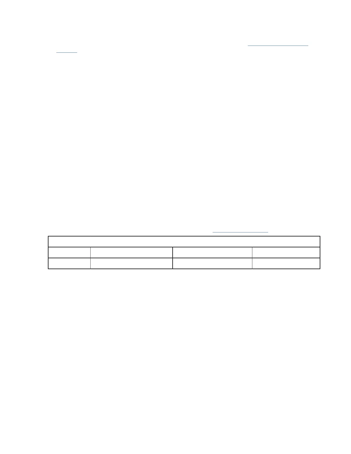
Combined Power Supply Redundancy Input Source Redundancy Full Redundancy
1 1 2 2
Table 15. Software Power Mode Grids Required
For information about the software power configuration modes, refer to the “Supported Transceivers”.
For information about the location of Grid A and Grid B power supply slots for each type of MDS 9700
Director chassis, refer to the chassis specific information at:
• Cisco MDS 9718 Chassis Front View
• Cisco MDS 9710 Chassis Front View
• Cisco MDS 9706 Chassis Front View
Before you connect a chassis power supply to an AC power source, ensure all of the following:
• There is a vacant receptacle on the AC power source within reach of the chassis power supply cable.
• The power supply is already installed in the chassis.
• The chassis is connected to an earth ground.
Note:
In a single phase AC power supply unit, connection of multiple phases from the same three-phase source
is supported and direct connection of three-phase is not supported.
To connect a 3-kW AC power supply directly to an AC power source, follow these steps:
1. Ensure that the power supply switch located on the front of the power supply is set at standby (labeled
as 0).
122IBM Storage Networking SAN192C-6, SAN384C-6 and SAN768C-6: SAN192C-6, SAN384C-6 and
SAN768C-6 Installation, Service, and User Guide
 Loading...