4 - 2
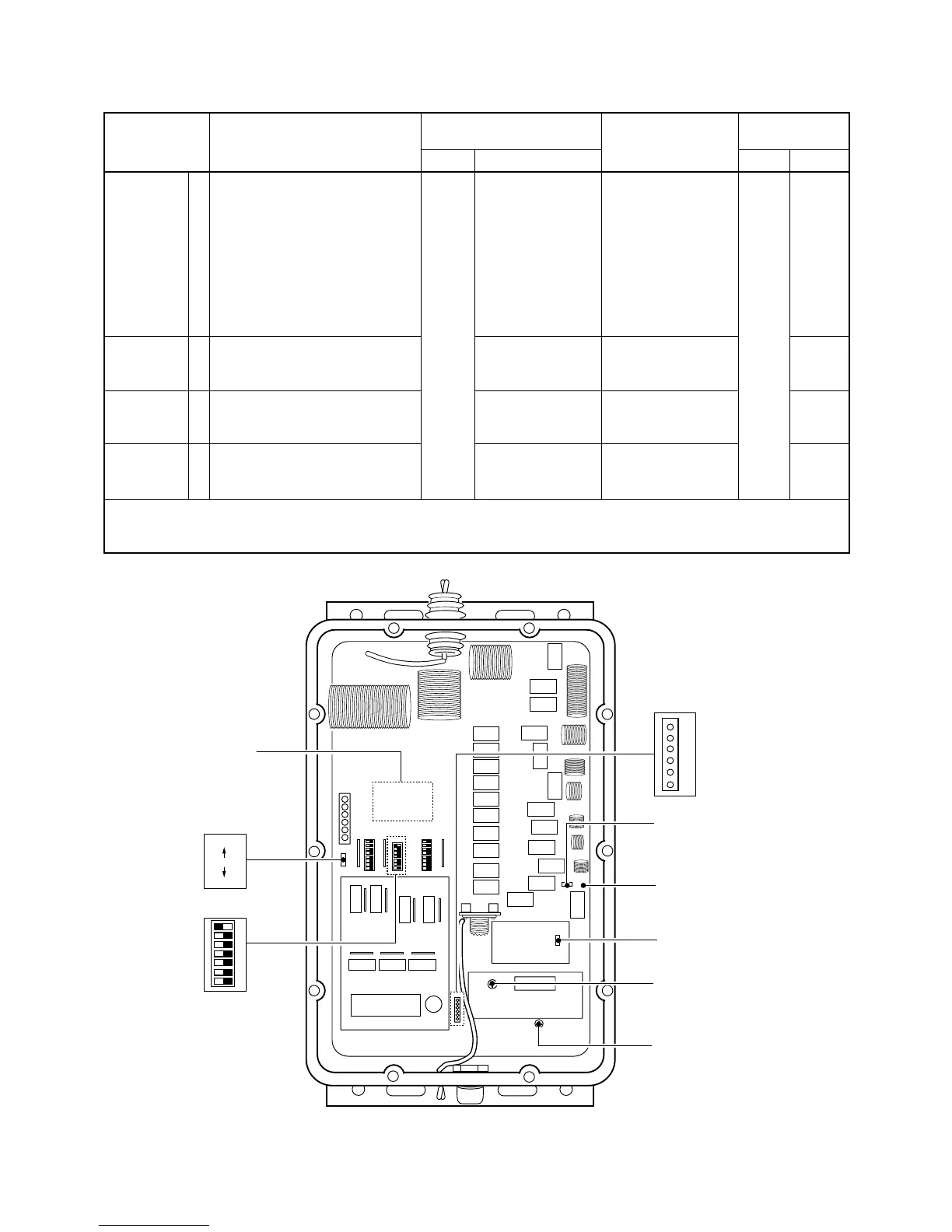
4-2 ANTENNA TUNER ADJUSTMENTS
PHASE
DETECTOR
CIRCUIT
IMPEDANCE
DETECTOR
CIRCUIT
FORWARD
DETECTOR
CIRCUIT
SWR
DETECTOR
CIRCUIT
ADJUSTMENT
ADJUSTMENT ADJUSTMENT CONDITION
MEASUREMENT
VALUE
POINT
UNIT LOCATION UNIT ADJUST
1
2
3
4
• S1 : PRESET
• S4-7 : OFF
• Short pins of J13.
• Disconnect P6 from J6.
• Ground J15 with a jumper wire.
• TRANSCEIVER
Display freq. : 1.6 MHz
Output power : 10 W
(carrer only)
Transmitting
• Same as above
• Same as above
• Same as above
Connect an oscillo-
scope to the check
point pin 2 of J8.
Connect an oscillo-
scope to check
point pin 3 of J8.
Connect an oscillo-
scope to check
point pin 1 of J8.
Connect an oscillo-
scope to check
point pin 4 of J8.
5 V (Tune R194 just
before droped.)
5 V (Tune C7 just
before drope.)
1.4 – 2.4 V
0 – 0.1 V
R56
C7
Verify
Verify
TUNER
TUNER
NOTE: • After adjustment, remove the jumper wires from J15 and ground.
• After adjustment, Disconnect pins of J13.
• After adjustment, reconnect P6 to J6 and set S1 to [NORMAL] position.
 Loading...