(Replacement page)
Feb. 2010
5 - 4
ADJUSTMENT
TRANSCEIVER’S
CONDITION
OPERATION
ADJUSTMENT
ITEM
VALUE
RECEIVE
SENSITIVITY
1 NOTE: When "RX SENSITIVITY" is re-adjusted, "S-METER" must be re-adjusted too.
• Frequency : 118.020 MHz
• Receiving
• Connect an SSG to the antenna connector
and set it as;
Frequency : 118.020 MHz
Level
†
: –6 dBµ (–113 dBm)
Modulation : 1 kHz
Deviation : ±3.5 kHz
[tr] Push [S.MW].
2 • Frequency : 136.020 MHz
• Receiving
• Set the SSG as;
Frequency : 136.020 MHz
3 • Frequency : 147.980 MHz
• Receiving
• Set the SSG as;
Frequency : 147.980 MHz
4 • Frequency : 173.980 MHz
• Receiving
• Set the SSG as;
Frequency : 173.980 MHz
SQUELCH 1 • Frequency : 145.020 MHz
• Receiving
1) Connect an SSG to the antenna
connector and set it as;
Frequency : 145.020 MHz
Level
†
: –20 dBµ (–127 dBm)
Modulation : 1 kHz
Deviation : ±3.5 kHz
2) Once close the squelch by increasing [Sq]
value, then decrease the value to open the
squelch.
3) Push [S.MW] to store the value.
[Sq] Push [S.MW].
S-METER
(FM mode)
1 NOTE: When "RX SENSITIVITY" must be adjusted before "S-METER." And when "RX SENSITIVITY" is re-
adjusted, "S-METER" must be re-adjusted too.
• Frequency : 145.020 MHz
• Receiving
1) Connect an SSG to the antenna
connector and set it as;
Frequency : 145.020 MHz
Level
†
: 2 dBµ (–105 dBm)
Modulation : 1 kHz
Deviation : ±3.5 kHz
2) Push [S.MW] to store the value.
[Sr] Push [S.MW].
(AM mode) 2 • Frequency : 127.020 MHz
• Receiving
1) Set the SSG to the antenna connector
and set it as;
Frequency : 127.020 MHz
Level
†
: 0 dBµ (–107 dBm)
Modulation : 1 kHz
Deviation : ±30%
2) Push [S.MW] to store the value.
[Sr+.] Push [S.MW].
†
; The output level of the standard signal generator (SSG) is indicated as the SSG’s open circuit.
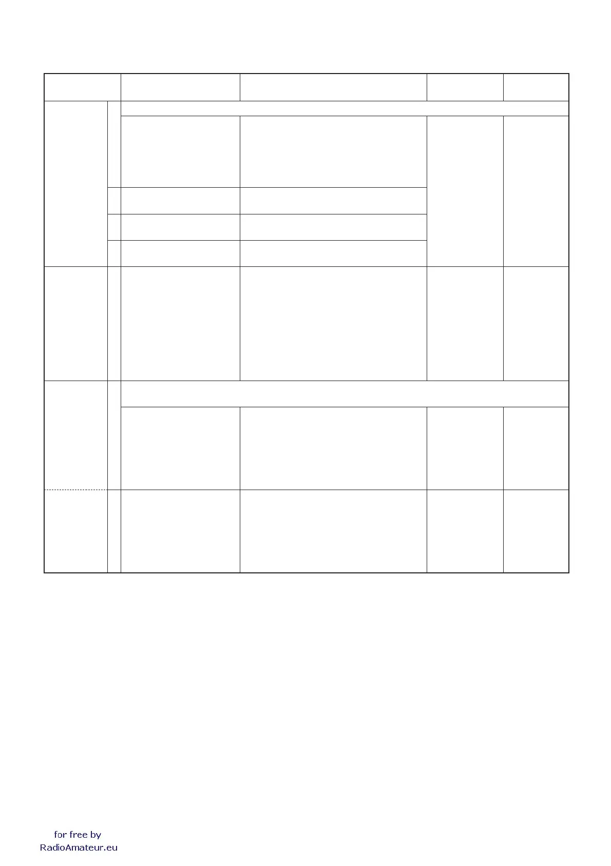
5-4 RECEIVE ADJUSTMENTS
1) Select an adjustment item using [BANK]/[V/MHz].
2) Set or modify the adjustment value as specifi ed using [DIAL], and then push [S.MW] to store the value.
 Loading...