INTRODUCTION
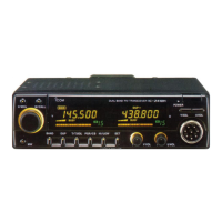
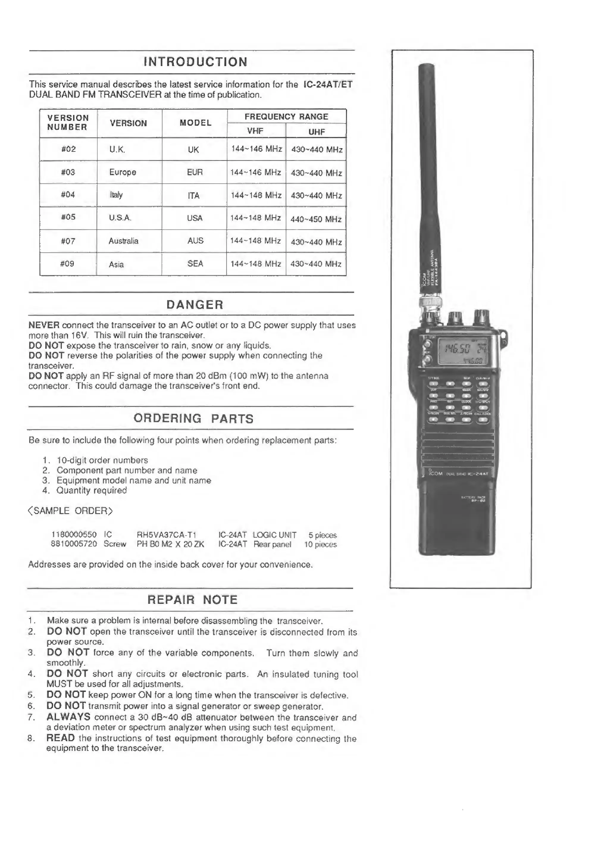
This service manual describes Ihe latest service information for the lC-24ATyET
DUAL BAND FM TRANSCEIVER at the time of publication.
VERSION
NUMBER
VERSION
MODEL
FREQUENCY RANGE
VHF
UHF
#02
U.K.
UK
1
44-'
146 MHz
#03 Europe EUR
144“146
MHz
430-440
MHz
#04
Jtafy
ITA
144'14B MHz
430-440
MHz
#05
U,S.A
USA
144-148
MHz
440-450
MHz
#07
Australia
AUS
144-148
MHz
430-440
MHz
#09
I
Asia
SEA
144-148
MHz
430-440
MHz
DANGER
NEVER connect the transceiver to an AC outlet or to a DC power supply that uses
more than
16V, This will ruin the transceiver.
DO NOT expose the
transceiver
to
rain,
snow or any
liquids,
DO
NOT reverse the polarities of the power supply when connecting the
transceiver
DO NOT
apply an
RF signal of more than 20 dBm
(100
mW) to the antenna
connector.
This could damage the transceiver's front end.
ORDERING
PARTS
Be
sure
to
include
the
following four
points when ordering replacement
parts:
1 . 1 0-d ig it order n umbers
2. Component part number and
name
3. Equipment model name and unit name
4. Quantity required
<SAMPLE
ORDER>
11S0000550 1C RH5VA37CA-T1 I024AT
LOGIC
UNIT
5
pieces
881 D005720 Screw PH
BO
MS
X 20 2K
I024AT
Rear panel
10
pieces
Addresses are provided on the inside back cover for your convenience.
REPAIR
NOTE
1 . Make sure a problem is
interral
before disassembling the transceiver.
2 . DO NOT
open the transceiver untN the
transceiver is disconnected from its
power source.
3.
DO
NOT
force any of
the
variable components. Turn them slowly and
smoothly.
4. DO NOT short any circuits or electronic parts.
An
Insulated
tuning tool
MUST be used for all adjustments.
6.
DO
NOT keep power ON
for
a
long
tirne
when the transceiver is detective.
6. DO NOT
transmit power into a signal generator or sweep
generator.
7. ALWAYS connect a 30 dB^40 dB attenuator between the
transceiver
and
a
deviation meter
or spectrum anafyier when using such test equipment,
5. READ the instructions of test equipment thoroughly
before
connecting the
equipment
to
the
transceiver.
 Loading...