3-2
UHF RECEIVER CIRCUITS
3-2-1
ANTENNA SWITCHING
CIRCUIT
(U-SW UNIT)
The antenna
switching
circuit is mainly the same as the VHP
band. Refer to Section
3-1 -1
for details. The following parts
are
different
from the VHP band:
The UHP signals pass through
the
high-pass filter
(LI, L2,
Cl ~C5 on the HPP UNIT) and
the
antenna switching
circuit
(L1. L2, C1~C3, D1 on the U-SW UNIT).
3-2-2
RF AND 1ST MIXER
CIRCUITS
(U-RF
UNIT)
The RP and 1st mixer circuits are located on the
U-RP
UNIT
where the signals are amplified at
Q1
and
Q2
,
and
are then
converted to
a
1st
IP
signal
at Q3. A frequency of the 1st IP
signal is 30.875 MHz.
Q3 converts
the RP signal using the U-PLL output coming
from the “HLO” line.
The UHP RP circuit adopts a helical coil bandpass filter circuit
(LI, L2) to suppress out-of-band signals.
3-2-3
IF, AF AND SQUELCH CIRCUITS
These
are the
same
as
the ones
commonly
used with
the
VHP
receiver
circuit.
Refer
to
Section
3-1-3~3-1-5
for
details.
3-3 VHF
TRANSMITTER
CIRCUITS
3-3-1
MIC
AMP
CIRCUIT
(MIC
UNIT)
The mic
amplifier
circuit
amplifies
audio
signals
with 6
dB/oct.
pre-emphasis
from
the
microphone
to a level
needed
for the
modulation
circuit.
The
MIC
UNIT has a
low
level
amplifier with
pre-emphasis
(IC3a) and a
limiter
amplifier
(IC3b).
3-3-2
MODULATION CIRCUIT
(V.PLL UNIT)
The modulation
circuit modulates the VCO
oscillating
signal
(RP signal) using
the microphone audio signal.
The audio signal from
the MIC UNIT (VMOD signal) changes
the
reactance of a varactor
diode
(02)
to modulate the
oscillated signal at the TX
VCO
(Q5).
The oscillated signal is
buffer-amplified at Q6 and
Q8,
and is then
applied
to the
drive amplifier circuit on the
MAIN
UNIT via
the “VLO” line.
3-3-3
DRIVE AND POWER
AMPLIFIER
CIRCUITS
(MAIN
UNIT)
The drive
amplifiers
(Q8, Q9)
and power
amplifier (IC1)
amplify the VCO
oscillating signal to an
output level.
Collector currents of the
drive amplifiers are controlled by
the APC
circuit (refer to Section
3-3-4
for
details).
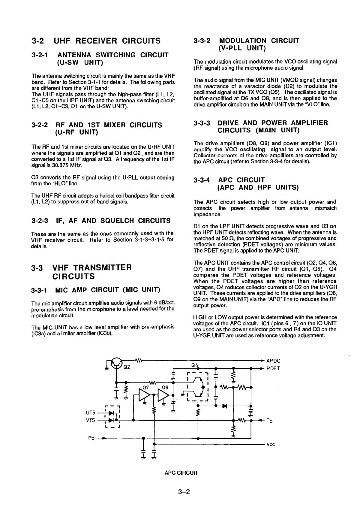
3-3-4
APC
CIRCUIT
(APC AND
HPF UNITS)
The APC circuit selects high or low
output power and
protects the power amplifier from antenna mismatch
impedance.
D1
on the LPP UNIT detects progressive wave
and
D3
on
the
HPP UNIT detects reflecting wave. When the
antenna
is
matched at 50
£i,
the
combined voltages of progressive and
reflective detection
(POET
voltages) are minimum
values.
The
PDET
signal is applied to the APC UNIT.
The APC UNIT contains the APC control
circuit
(Q2,
Q4,
Q6,
Q7)
and the UHP
transmitter
RP
circuit
(Q1,
Q5).
Q4
compares the PDET voltages and reference
voltages.
When the PDET voltages
are higher than reference
voltages, Q4 reduces collector currents of Q2
on the U-YGR
UNIT. These currents are applied to the
drive amplifiers
(Q8,
Q9
on the MAIN UNIT) via the “APD” line to
reduces the RP
output
power.
HIGH or LOW
output power is determined with the reference
voltages of the APC
circuit.
IC1
(
pins
6
,
7
)
on the lO UNIT
are
used as
the power selector ports and R4 and
Q3
on the
U-YGR
UNIT are used as reference voltage
adjustment.
APDC
PDET
Po
Vcc
3-2
 Loading...