SECTION 4
CIRCUIT
DESCRIPTION
4-1
RECEIVER
CIRCUITS
4-1-1
RF
SWITCHING
CIRCUIT
(PA AND
MAIN
UNITS)
RF signals
from the
antenna connector pass
through the
transmit/receive
switching
relay (RL13) and
a low-pass
filter,
and are
applied
to
the MAIN
UNIT via P2 (MAIN
UNIT: J12).
The
signals
from the PA
UNIT either bypass
or
are
attenuated at 20 dB
attenuator (R102,
R103, RL1). There
are no
non-linear
components
between the antenna
connector
and attenuator
to prevent
distortion caused
by
strong signals.
The signals
are then
applied to RF
filters.
4-1-2
RF
BANDPASS
FILTER CIRCUIT
(MAIN
UNIT)
The
RF UNIT has
7 RF bandpass
filters
(BPF) for signals
above
1.6
MHz
and
1 low-pass
filter (LPF)
for signals below
1.6 MHz.
The signals pass
through one of the bandpass
or low-pass
filters depending
on the
receive
frequency
range.
(1)
0.5~1.6 MHz
A
diode is not used at
the low-pass
filter entrance
removing
diode
distortion from
very strong signals.
Signals bypass a
preamplifier by the
bypass switch
(Q12).
(2)
1.6 MHz
AND ABOVE
Signals are
applied
to a
high-pass
filter
consisting of
L42,
L43, C143~C146.
This filter suppresses
strong signals
below 1.6 MHz such as a
broadcasting
station.
The filtered
signals are
applied
to
one
of 7 bandpass filters
depending on the frequency
of the signals
and then
to
the
preamplifier circuit
(Q8,
Q9).
(3)
FILTER SWITCHING
CIRCUIT
An RF bandpass
filter is selected
with BPF switching
voltage
(B0~B7) from the CPU
via IC16
current amplifier.
The
switching voltage of the BPF
entrance is
higher
than
the BPF exit to
improve multi-signal and
strong signal
characteristics.
4-1-3
PREAMPLIFIER CIRCUIT
(MAIN UNIT)
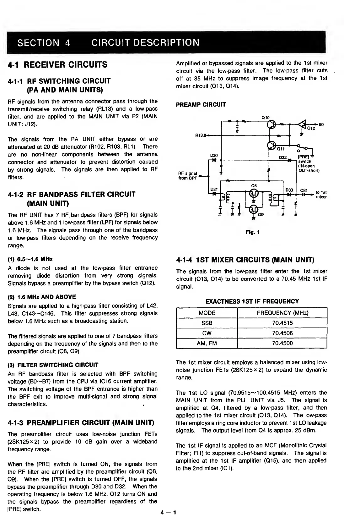
The
preamplifier circuit uses low-noise
junction FETs
(2SK125X2)
to
provide
10
dB
gain over a wideband
frequency range.
When the
[PRE] switch is
turned
ON,
the signals from
the RF
filter are amplified by the
preamplifier
circuit
(Q8,
Q9).
When the [PRE]
switch is turned OFF,
the signals
bypass
the
preamplifier through D30
and D32. When the
operating
frequency
is
below 1.6 MHz, 012 turns
ON and
the
signals bypass the
preamplifier regardless of the
[PRE]
switch.
Amplified or bypassed
signals
are applied to
the 1 st
mixer
circuit via
the low-pass
filter.
The low-pass
filter cuts
off at 35
MHz to
suppress
image
frequency at
the 1st
mixer circuit
(013,
014).
PREAMP
CIRCUIT
Q10
4-1-4
1ST MIXER CIRCUITS
(MAIN UNIT)
The signals
from the low-pass
filter enter the 1st mixer
circuit
(013, 014)
to be
converted to a
70.45 MHz 1st IF
signal.
EXACTNESS 1ST
IF FREQUENCY
MODE FREQUENCY (MHz)
SSB
70.4515
CW
70.4506
AM, FM
70.4500
The
1 St
mixer circuit
employs a
balanced mixer
using low-
noise
junction FETs
(2SK125x2)
to expand the
dynamic
range.
The 1st LO signal (70.951
5~1
00.451
5
MHz) enters the
MAIN UNIT
from
the PLL
UNIT via
J5.
The
signal is
amplified at
04,
filtered by a
low-pass
filter,
and
then
applied
to
the 1st mixer
circuit
(Q13,
014).
The
low-pass
filter employs
a
ring core inductor to prevent 1 st LO
leakage
signals. The output level
from Q4 is approx. 25 dBm.
The 1st IF
signal is applied
to
an
MCF (Monolithic Crystal
Filter; FI1) to suppress out-of-band
signals. The signal is
amplified at the 1st IF
amplifier
(015),
and then applied
to
the 2nd mixer
(101).

 Loading...