3 - 2
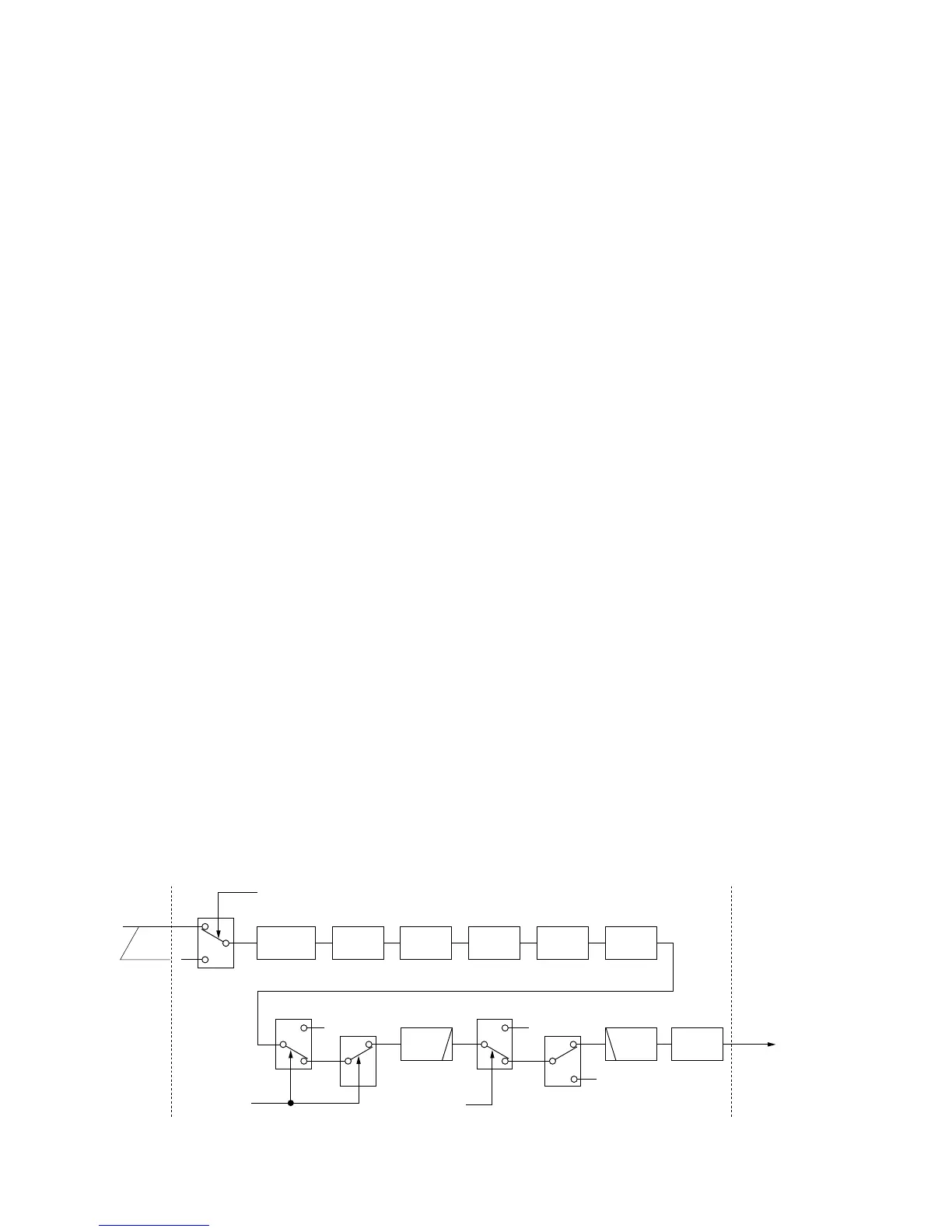
3-1-5 1ST IF CIRCUIT (RF UNIT)
The 1st IF circuit filters and amplifies the 1st IF signal. The
1st IF signal combined at L653 is applied to an MCF
(Monolithic Crystal Filter; FI711a/b) to suppress out-of-band
signals.
The converted 1st IF signal level is adjusted at PIN attenua-
tors (D531–D533, D535 or D631–D632, D635) controlled by
the [BAL] controller for the dualwatch function. The signal is
applied to the 1st IF amplifier (Q551 or Q651) and then com-
bined at L653.
The combined signal passes through the MCFs (FI711a/b)
and PIN attenuator (D781, D783). The signal is amplified at
the 1st IF amplifier (Q721). The amplified signal is then
applied to the 2nd mixer circuit.
3-1-6 2ND MIXER CIRCUIT (RF UNIT)
The 2nd mixer circuit mixes the amplified 1st IF signal and
2nd LO signal (64.00 MHz) for conversion into the 2nd IF
signal.
The 1st IF signal from the 1st IF amplifier (Q721) is convert-
ed into a 455 kHz 2nd IF signal at the 2nd mixer circuit
(Q941–Q944).
The 2nd IF signal is applied to the ceramic filter (MAIN unit,
FI131) to suppress un-desired signals, and then applied to
the noise blanker gate.
3-1-7 NOISE BLANKER CIRCUIT (MAIN UNIT)
The noise blanker circuit detects pulse-type noise, and turns
OFF the signal line when the noise appears.
The 2nd IF signal from the ceramic filter (FI132) is applied to
the noise blanker gate (D112, D116). A portion of the signal
from FI132 is amplified at the noise amplifiers (Q271–Q273),
and is then detected at the noise detector (D271) to convert
the noise components to DC voltages.
The signal is then applied to the noise blanker switch (Q276,
Q278). At the moment the detected voltage exceeds Q276’s
threshold level, Q278 outputs a blanking signal to close the
noise blanker gate (D112, D116). The PLL unlock signal are
also applied to Q278, to control the noise blanker gate.
Some DC voltage from the noise detector circuit is fed back
to the noise amplifiers (Q271–Q273) via the DC amplifiers
(Q274, Q275). The DC amplifiers function as an AGC circuit
to reduce average noise. Therefore, the noise blanker func-
tion shuts off pulse-type noise only.
3-1-8 2ND IF CIRCUIT (MAIN UNIT)
The 2nd IF circuit filters and applies the 2nd IF signal to the
3rd mixer circuit.
The 2nd IF signal from the noise blanker gate (D112, D116)
is passed through the another ceramic filter (FI111). The fil-
tered signal is applied to the 3rd mixer circuit.
3-1-9 3RD MIXER AND 3RD IF CIRCUITS
(MAIN UNIT)
The 3rd mixer circuit mixes the 2nd IF signal and the 3rd LO
signal to obtain the 3rd IF (36 kHz) signal.
The 2nd IF signal from the ceramic filter (FI111) is applied to
the 3rd mixer circuit (IC151, pin 1). The 3rd LO signal from
the PLL unit is applied to the 3rd mixer (IC151, pin 10). The
mixed signal is output from pin 6.
The 3rd IF signal is amplified at the 3rd IF amplifier
(IC201b), and is passed through the low-pass filter (IC201a)
The filtered signal is then applied to the DSP board via DRIF
line.
3-1-10 DSP RECEIVER CIRCUIT (DSP BOARD)
The DSP (Digital Signal Processor) board enables digital IF
filter, digital noise reduction, digital PSN (Phase Shift
Network)/Low Power/Phase demodulation, digital automatic
notch, and etc.
The 36 kHz 3rd IF signal from the low-pass filter (MAIN unit,
IC201a) is amplified at the differential amplifiers (IC2301a/b)
after being passed through the T/R switch (IC2291), and is
then applied to the A/D converter (IC2321). The coverted
signal is level shifted 5V to 3.3 V at the level converter
(IC2051).
 Loading...