SECTION 3 CIRCUIT DESCRIPTION
3 - 1
3-1 RECEIVER CIRCUITS
3-1-1 RF SWITCHING CIRCUIT
(CTRL AND RF UNITS)
The RF switching circuit leads receive signals to bandpass
filters from an antenna connector while receiving. However,
the circuit leads the signal from the RF power amplifier to the
antenna connector while transmitting.
RF signals from [ANT 1] or [ANT 2] pass through the anten-
na selector (RL3), transmit/receive switching relays (RL1,
RL2, RL4), and low-pass filter (L27, L28, C63–C66, C105),
and are then applied to the RF unit via J2.
The signals from the CTRL unit either bypass or pass
through the 6 dB (RF unit, RL121, R121) and/or 12 dB (RF
unit, RL122, R123) attenuators via the antenna selector
(RL101). By selecting the attenuators, 0 (bypass), 6, 12 and
18 dB attenuations are obtained. The signals are then
applied to the RF filters.
When the [RX ANT] is selected, the RF signals are passed
through the low-pass filter (RF unit, L112, L111,
C111–C116), then applied to the antenna selector (RF unit,
RL101).
3-1-2 RF BANDPASS FILTER CIRCUIT (RF UNIT)
RF bandpass filters pass only the desired band signals and
suppress any undesired band signals. The RF circuit has 11
bandpass filters and 1 low-pass filter.
(1) 0.03–1.6 MHz
The signals pass through the low-pass filter (L181–L183,
C181–C185), attenuator (R181–R183), and are then applied
to the RF amplifiers (Q501, Q601).
(2) 1.6–60 MHz
The signals pass through the high-pass filter (L171–L174,
C171–C174) to suppress excessively strong signals below
1.6 MHz. The filtered signals are applied to one of 11 band-
pass filters as below, and then applied to or bypassed the
pre-amplifier circuit.
3-1-3 PRE-AMPLIFIER CIRCUITS (RF UNIT)
The IC-756PRO has 2 gain levels of pre-amplifier circuits.
One has 10 dB gain over a wide band frequency range and
the other one has 16 dB gain for the 21–28 MHz bands.
When the [PREAMP] switch is set to [PRE1] or [PRE2], the
signals are applied to the pre-amplifier 1 (Q441, Q442) or
pre-amplifier 2 (IC451) circuit, respectively. Pre-amplified or
bypassed signals are applied to the RF amplifier circuits
(Q501, Q601).
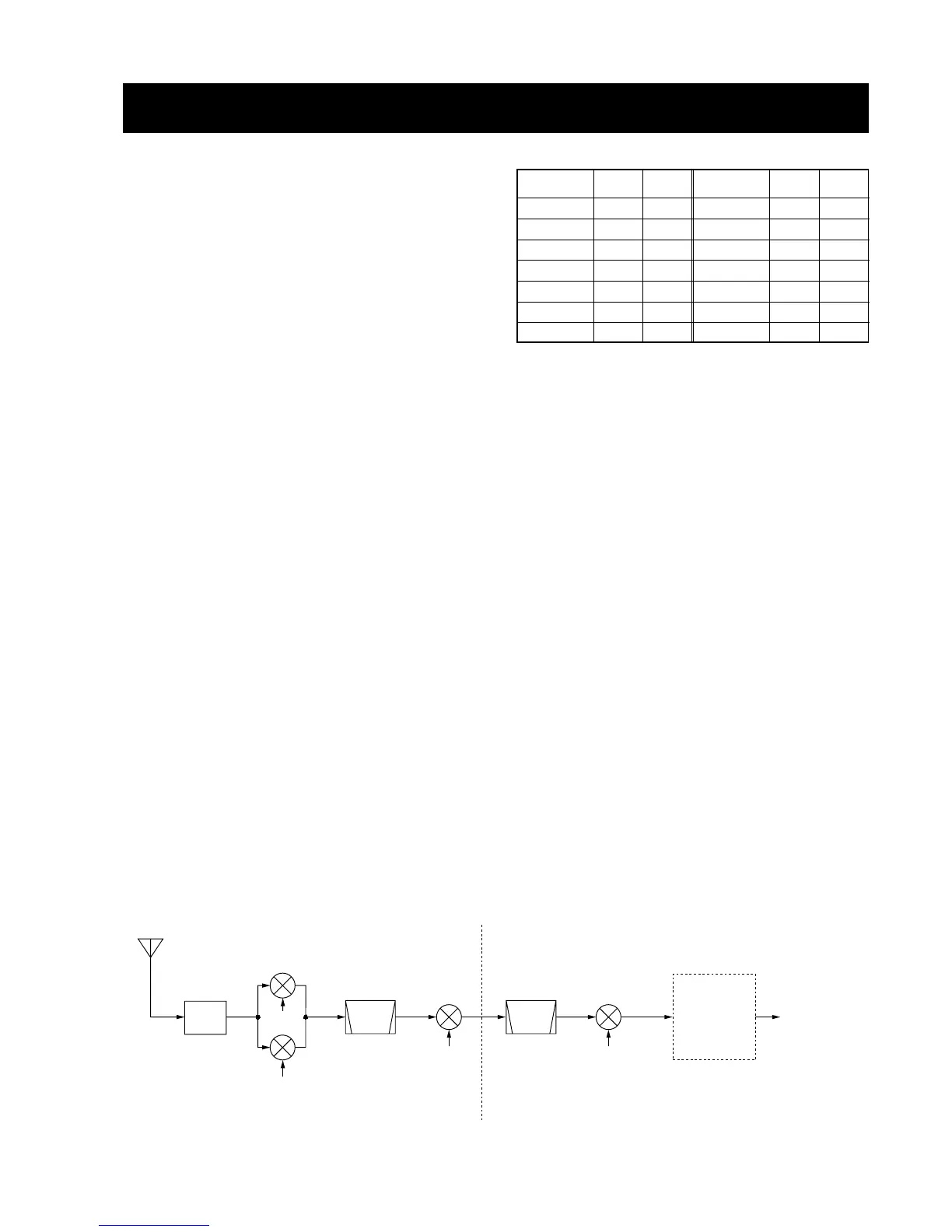
3-1-4 RF AMPLIFIER AND 1ST MIXER CIRCUITS
(RF UNIT)
The 1st mixer circuit mixes the receive signals with the 1st
LO signal to convert the receive signal frequencies into a
64.455 MHz 1st IF signal. The IC-756PRO has two 1st mixer
circuits for the dualwatch function.
The signals from the pre-amplifier circuit, or signals which
bypass the pre-amplifiers, are divided at L491. Each signal
is applied to a 60 MHz cut-off low-pass filter, RF amplifier
(Q501, Q601) and then to a 1st mixer (Q511–Q514 or
Q611–Q614).
Each 1st LO signal (64.4850–124.4550 MHz) enters the RF
unit from the PLL unit via J561 or J661. The LO signals are
amplified at the LO amplifier (Q561 or Q661), filtered by a
low-pass filter, and then applied to each 1st mixer.
• Used RF filter
 Loading...