5 - 3
5-2 PLL AND TRANSMITTER ADJUSTMENTS
• The “PLL LOCK VOLTAGE” adjustment must be performed at the “NORMAL” mode.
• “REFERENCE FREQUENCY”, “IDLING CURRENT”, “OUTPUT POWER” AND ‘AM MODULATION” adjustments must be per-
formed at the “ADJUSTMENT” mode.
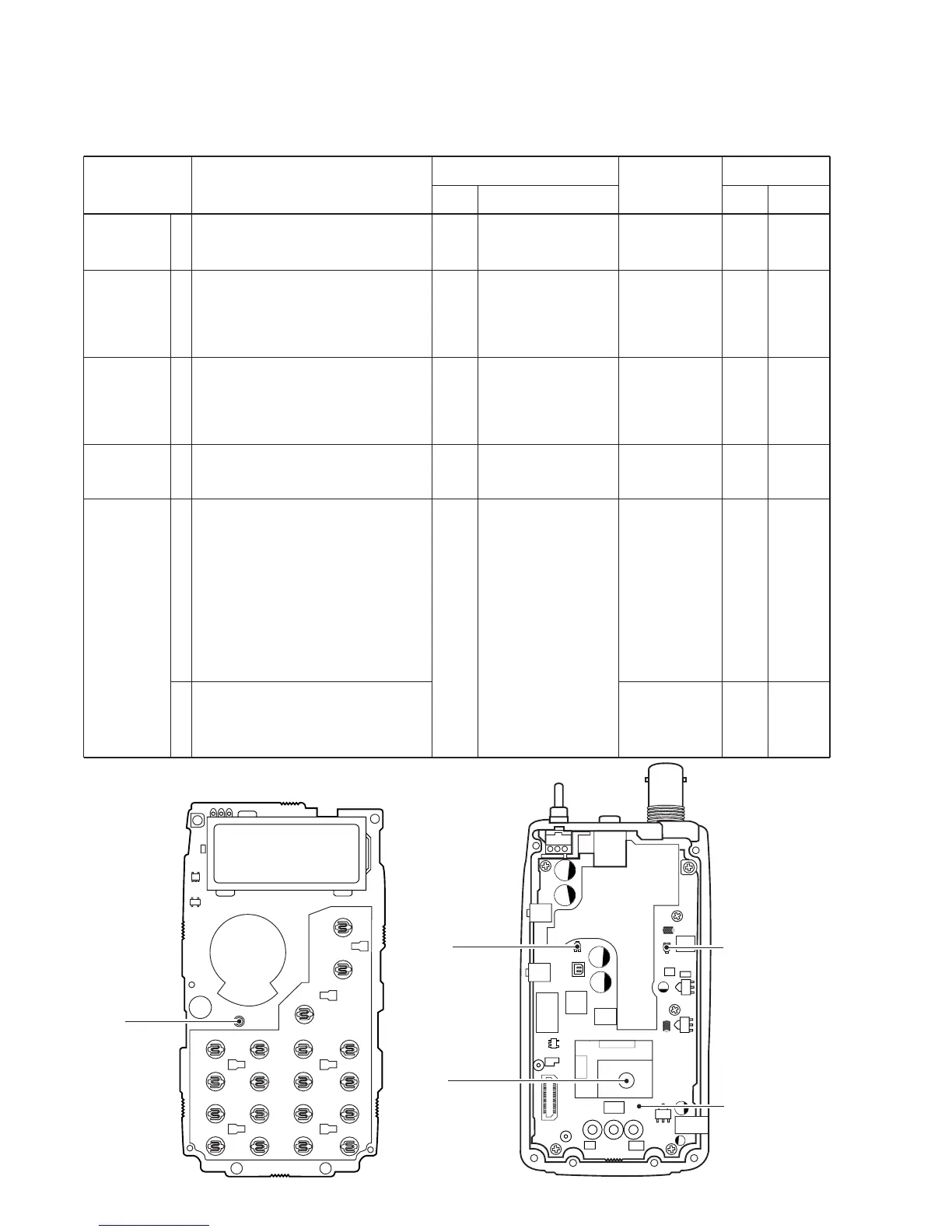
• LOGIC UNIT TOP VIEW
• RF UNIT TOP VIEW
PLL LOCK
VOLTAGE
REFERENCE
FREQUENCY
IDLING
CURRENT
OUTPUT
POWER
AM
MODULATION
[PWRADJ]
1
1
1
1
1
2
• Operating frequency: 136.975 MHz
• Receiving
• Operating channel : 0 ch
[FREQADJ]
(136.975 MHz)
• Connect the RF power meter or a 50 Ω
dummy load to the antenna connector.
• Transmitting
• Operating channel : 1 ch [PWR-1]
(136.975 MHz)
• Connect the RF power meter or a 50 Ω
dummy load to the antenna connector.
• Transmitting
• Operating channel : 2 ch [PWRADJ]
(136.975 MHz)
• Transmitting
• Operating channel : 2 ch [PWRADJ]
(136.975 MHz)
• Connect an audio generator to the
[MIC] connector and set as :
1 kHz/200 mV
• Set a modulation analyzer as :
HPF : OFF
LPF : OFF
De-emphasis : OFF
Detector : (P-P)/2
• Transmitting
• Connect an audio generator to [MIC]
connector and set as :
1 kHz/20 mV
• Transmitting
RF
Top
panel
Side
panel
Top
panel
Top
panel
Connect a digital multi
meter to the check
point CP1.
Loosely couple the fre-
quency counter to the
antenna connector.
Connect a DC amme-
ter between the DC
power supply and
transceiver’s DC
power jack.
Connect an RF power
meter to the antenna
connector.
Connect a modulation
analyzer to the anten-
na connector via an
attenuator.
3.7 V
136.9750 MHz
600 mA
1.5 W
85 %
30 %
RF
Top
panel
RF
Top
panel
RF
LOGIC
L40
[DIAL]
R16
[DIAL]
R554
R41
ADJUSTMENT ADJUSTMENT CONDITIONS
UNIT LOCATION
VALUE
UNIT ADJUST
MEASUREMENT ADJUSTMENT
 Loading...