ADJUSTMENT PROCEDURE
M REQUIRED EQUIPMENTS
5-1 PREPARATION
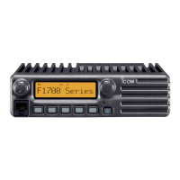
M JIG CABLE
3-conductor 2.5 (d) mm plug
(MIC)
(GND
)
33 k
3-conductor 3.5 (d) mm plug
(CLONE)
OPC-478UC
(GND)
(SP)
[JIG cable1]
[JIG cable2]
+−
AC MILLIVOLTMETER
(10 mV to 10 V)
AUDIO GENERATOR
(300–3000 Hz/1–500 mV)
+−
PTT
+
4.7 µF
EXTERNAL SPEAKER
(1 W/8 Ω)
+
−
SETTING;
Frequency : 1 kHz
Level :150 mV
Waveform : Sine wave
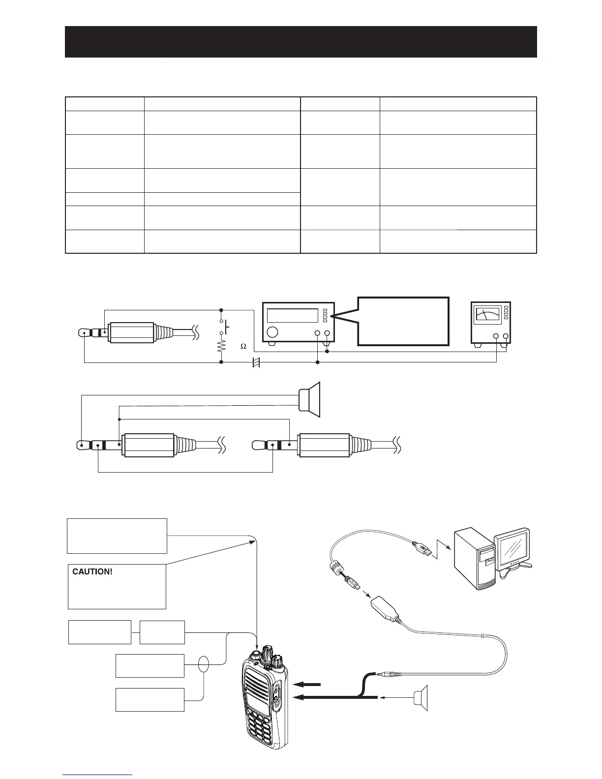
M CONNECTION
FM
deviation meter
to the antenna connector
Attenuator
30 dB
RF power meter
0.1– 10 W/50 Ω
Frequency
counter
Standard signal generator
–20 to 90 dBµ
(–127 to –17 dBm)
NEVER transmit while
an SSG is connected to
the antenna connector.
PC
to USB port
OPC-478UC
Speaker (8 Ω)
To [SP]
To [MIC]
(JIG cable 1)
(JIG cable 2)
IC-F1000/IC-F1000T/
IC-F1000S/IC-F1000T-T
To [SP] connector
EQUIPMENT GRADE AND RANGE EQUIPMENT GRADE AND RANGE
Cloning software
CS-F2000 CLONING SOFTWARE
(Revision 1.0 or later)
JIG cable
Modifi ed OPC-478UC
(See the illust below)
RF power meter
(50
terminated)
Measuring range : 0.1–10 W
Frequency range : 100–300 MHz
SWR : Less than 1.2 : 1
Frequency counter
Frequency range : 0.1–300 MHz
Frequency accuracy : ±1 ppm or better
Input level : Less than 1 mW
Modulation
Analyzer
Frequency range : 30–300 MHz
Measuring range : 0 to ±10 kHz
Standard signal
generator (SSG)
Frequency range : 0.1–300 MHz
Output level : –20 to 90 dBµ
(–127 to –17 dBm)
AC millivoltmeter Measuring range : 10 mV to 10 V
Oscilloscope
Frequency range : DC–20 MHz
Measuring range : 0.01–20 V
Attenuator
Power attenuation : 30 dB
Capacity : More than 10 W
Audio generator
(AG)
Frequency range : 300–3000 Hz
Output level : 1–500 mV
External speaker
Input impedance : 8
Capacity : More than 1 W
 Loading...