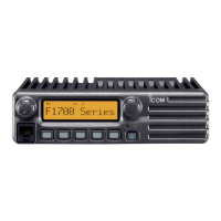
5-4
ADJUSTMENT
TRANSCEIVER’S
CONDITION
OPERATION
ADJUSTMENT
ITEM
VALUE
PLL LOCK
VOLTAGE
-Preparation-
1
–
1) Connect an RF power meter to the
antenna connector.
2) Set the preset adjustment value on the
adjustment utility window.
LV (RX LVA FL) 46
(0.9 V)
LV (TX LVA FL)
LV (RX LVA FH) 255
(5.0 V)
LV (TX LVA FH)
-ADJUSTMENT-
(RX Band low)
2• Select the item [RX LVA Start], then push [ENTER] to enter the
lock voltage adjustment mode.
[RX LVA Start]
–
3 • Channel: 1-1
• Receiving
• Select the item [RX LVA FL], then push
[ENTER].
[RX LVA FL]
0.9 V
4• Select the item [RX LVA Start], then push [ENTER]. [RX LVA Start] –
(RX Band high) 5 • Channel: 1-2
• Receiving
• Set the item adjustment value in the [RX
LVA FH] on the adjustment utility window,
then push [ENTER].
[RX LVA FH]
255
(5.0 V)
6• Select the item [RX LVA Start], then push [ENTER] to quit the
lock voltage adjustment mode.
[RX LVA Start]
–
-ADJUSTMENT-
(TX Band low)
7• Select the item [TX LVA Start], then push [ENTER] to enter the
lock voltage adjustment mode.
[TX LVA Start]
–
8 • Channel: 1-1
• Receiving
• Select the item [TX LVA FL], then push
[ENTER].
[TX LVA FL]
0.9 V
9• Select the item [TX LVA Start], then push [ENTER] to quit the
lock voltage adjustment mode.
[TX LVA Start]
–
(TX Band high) 10 • Channel: 1-2
• Receiving
• Set the item adjustment value in the [TX
LVA FH] on the adjustment utility window,
then push [ENTER].
[TX LVA FH]
255
(5.0 V)
11
• Select the item [TX LVA Start], then push [ENTER] to quit the
lock voltage adjustment mode.
[TX LVA Start]
–
PLL LOCK
VOLTAGE
-Verify-
(RX Band low)
1 • Channel: 1-3
• Receiving
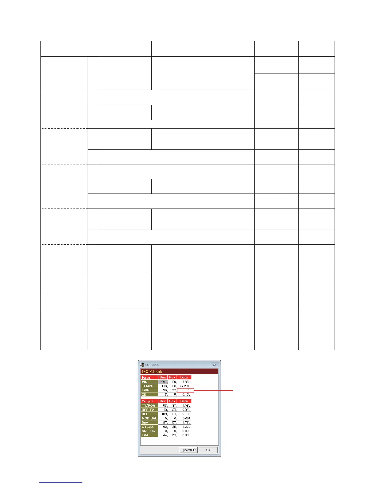
• Click the [Reload (F5)] button to check on
the "I/O Check window" as below.
[LVIN]
(On the "I/O
Check window")
0.9 V ±0.2 V
(Verify)
(RX Band high) 2 • Channel: 1-4
• Receiving
Less than
3.5 V
(Verify)
(TX Band low) 3 • Channel: 1-3
• Transmitting
0.9 V ±0.2 V
(Verify)
(TX Band high) 4 • Channel: 1-4
• Transmitting
Less than
3.5 V
(Verify)
REFERENCE
FREQUENCY
1 • Channel: 1-5
• Transmitting
• Loosely couple a frequency counter to the
antenna connector. [REF]
174.000000
MHz
(±150 Hz)
5-2 FREQUENCY ADJUSTMENTS
1) Select an adjustment item using [
]/[
] on the PC's keyboard.
2) Set or modify the adjustment value as specifi ed using [
]/[
] on the PC's keyboard, and then push [ENTER].
• I/O Check window
(The values shown above are only examples.
Each transceiver has own values.)
* * *
Lock voltage
 Loading...