6 - 4
6-2 FREQUENCY ADJUSTMENT
Select an adjustment item using [
↑
] / [
↓
] keys, then set to the specifi ed value using [
←
] / [
→
] keys on the connected PC's keyboard.
ADJUSTMENT ADJUSTMENT CONDITION
MEASUREMENT
VALUE
UNIT OPERATION
PLL LOCK
VOLTAGE
[RX LVA1]
1 • Channel
• Lock voltage preset
[LV (RX1)]
• Receiving
: CH 1
: 164 [3.2 V]
PC
screen
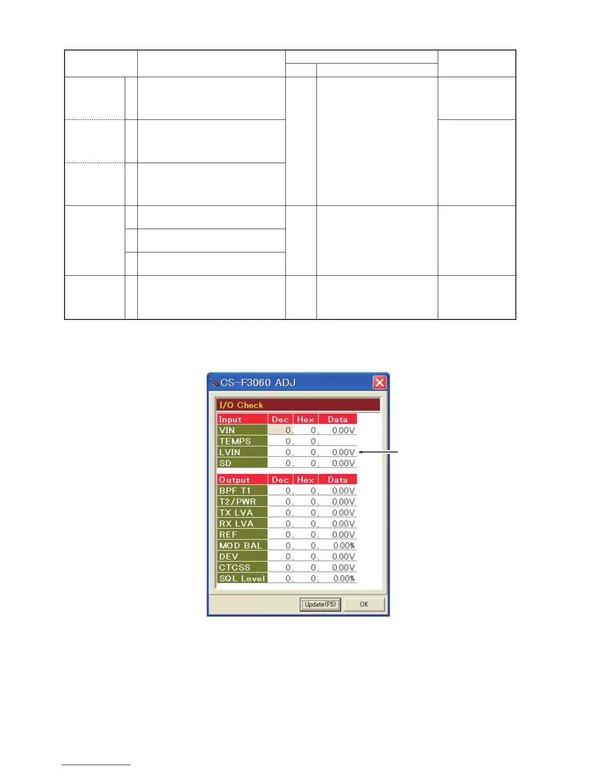
Click [I/O Check] in the Clone
menu to open the "I/O Check
window."
Click [Update (F5)] button, then
check the "LVIN" item on the
adjustment software’s screen as
below.
3.2 V
[RX LVA2] 2 • Channel
• Lock voltage preset
[LV (RX2)]
• Receiving
: CH 2
: 153 [3.0 V]
3.0 V
[TX LVA] 3 • Channel
• Lock voltage preset
[LV (TX)]
• Transmitting
: CH 2
: 153 [3.0 V]
PLL LOCK
VOLTAGE
1 • Channel
• Receiving
: CH 3 PC
screen
Click [Update (F5)] button, then
check the "LVIN" item on the
adjustment software’s screen.
0.6–1.6 V
(Verify)
2 • Channel
• Receiving
: CH 4
3 • Channel
• Transmitting
: CH 3
REFERENCE
FREQUENCY
[REF]
• Channel : CH 2 Top
panel
Loosely couple a frequency
counter to the antenna connec-
tor.
173.90000 MHz
• Connect an RF power meter to the
antenna connector.
• Transmitting
• I/O Check window
Lock voltage check
NOTE:
The above values are example only.
Each transceiver has its own specific values for each item.
 Loading...