6 - 5
6-3 TRANSMIT ADJUSTMENT
Select an adjustment item using [
↑
] / [
↓
] keys, then set to the specifi ed value using [
←
] / [
→
] keys on the connected PC's keyboard.
ADJUSTMENT ADJUSTMENT CONDITION
MEASUREMENT
VALUE
UNIT OPERATION
OUTPUT
POWER
[Power (Hi)]
1 • Channel
• Transmitting
: CH 6 Top
panel
Connect an RF power meter to
the antenna connector.
5.0 W
[Power (L2)] 2 • Channel
• Transmitting
: CH 5 2.0 W
[Power (L1)]
(Other than
[FRG-01])
3 • Channel
• Transmitting
: CH
4
1.0 W
([FRG-01] only)
• Channel
• Transmitting
: CH 2 1.15 W
MODULATION
BALANCE
[BAL (Narrow)]
1 • Channel
• Preset [MOD Narrow]
: CH 4
: 60
Top
panel
Connect the FM deviation me-
ter to the antenna connector
through an attenuator.
• No audio applied to the JIG cable.
• Set an FM deviation meter same as;
HPF
LPF
De-emphasis
Detector
: OFF
: 20 kHz
: OFF
: (P–P)/2
• Push [P0] key while transmitting.
FM
DEVIATION
(NARROW)
[MOD N C]
1
• Channel : CH 7
Top
panel
Connect the FM deviation me-
ter to the antenna connector
through an attenuator.
±2.05 to ±2.15 kHz
• Connect an audio generator to the JIG
cable and set as;
Frequency : 1.0 kHz
Level : 150 mV rms
• Set the FM deviation meter to same condi-
tion as "MODULATION BALANCE."
• Transmitting
(NARROW)
[MOD N L]
2
• Channel
• Transmitting
: CH 8
(NARROW)
[MOD N H]
3
• Channel
• Transmitting
: CH 9
(WIDE)
[MOD W C]
4
• Channel
• Transmitting
: CH 13
±4.05 to ±4.15 kHz
(WIDE)
[MOD W L]
5
• Channel
• Transmitting
: CH 14
(WIDE)
[MOD W H]
6
• Channel
• Transmitting
: CH 15
(MIDDLE)*
[MOD M C]
7
• Channel
• Transmitting
: CH 10
±3.20 to ±3.30 kHz
(MIDDLE)*
[MOD M L]
8
• Channel
• Transmitting
: CH 11
(MIDDLE)*
[MOD M H]
9
• Channel
• Transmitting
: CH 12
DIGITAL
DEVIATION**
[MOD D C]
1
• Preset [Digital Mode] : 7
Top
panel
Connect an FM deviation meter to
the antenna connector through
an attenuator.
±1.35 to ±1.39 kHz
2
• Channel : CH 16
• Set the FM deviation meter to same condi-
tion as "MODULATION BALANCE."
• Transmitting
[MOD D L] 3
• Channel
• Transmitting
: CH 17
[MOD D H] 4
• Channel
• Transmitting
: CH 18
*; [F3062], [F3162] only. Necessary and sufficient FM DEVIATION adjustment for [FRG-01].
**; Necessary only when the optional UT-119H or UT-126H is installed. Not necessary for [FRG-01].
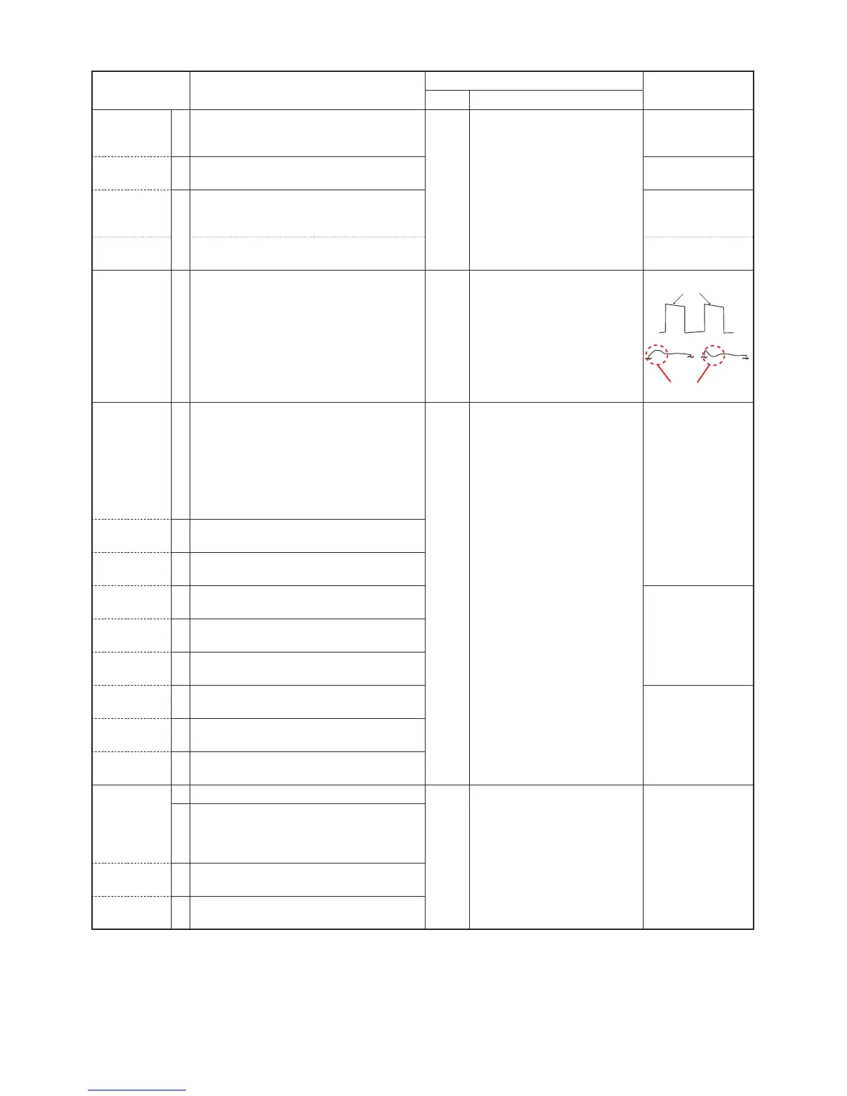
No over or under shoot.
As flat as possible.
 Loading...