4 - 2
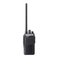
RX AF CIRCUITS
The demodulated AF signal from the linear codec (IC902) is
passed through the LPF (IC60C), and then adjusted in level
by the D/A converter (IC57). The level-adjusted AF signal is
then amplifi ed by AF AMPs (IC58 and IC55).
The amplifi ed AF signal is applied to the internal or external
speaker.
SQUELCH CIRCUITS (Analog mode only)
The squelch circuit cuts off the AF output signals when no
RF signals are received. Detecting noise components in the
demodulated AF signals, the squelch circuit stops audio sig-
nals being emitted.
A portion of demodulated AF signal from the IF IC (IC3) is
passed through the D/A converter (IC57) for level (=thresh-
old) adjustment. The level-adjusted AF signals are passed
through the noise filter (IC3, pins 7, 8 and R139–R142,
C241–C243) to fi lter the noise components (approx. 30 kHz
signals) only. The noise components are rectified, resulting
in DC voltage corresponding to the noise level.
If the noise level is higher than the preset one, the internal
comparator set the “NOISE” signal to the CPU to “High”,
then the CPU turns the “AFON” signal which controlls the AF
power AMP (IC55) to “Low,” to inactivate it.
• RX AF CIRCUITS
• SQUELCH CIRCUITS
AF
AM P
AF
AMP
IC55 TPA0211DGN
J52
SP1
AF
AM P
J53
Int.speaker
Ext.speaker
1
2
LPF
IC60C
From the linear codec
IC58
AFON
AFO
DAFO
D/A
converter
IC57
DAC
Noise
AMP
Noise filter
From IF IC
(IC3, Pin16)
To RX AF circuits
Noise
detector
Com-
parator
NOISE SQUELCH DIAGRAM
“NOIS”
IC57
IC3
14
8
7
13
15
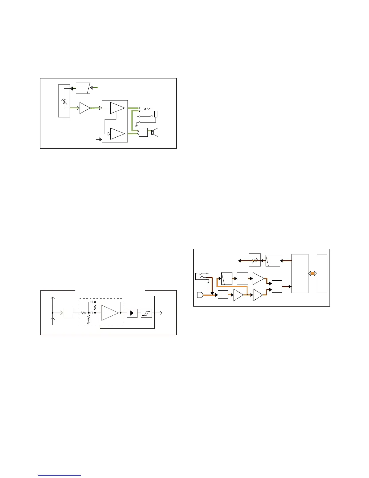
4-2 TRANSMITTER CIRCUITS
TX AF CIRCUITS
The audio signal from the internal or external microphone
(MIC signal) is passed through the MIC gain SW (IC62), and
then applied to the MIC AMP (IC64).
• WHILE OPERATING IN THE ANALOG MODE
The amplifi ed MIC signal is passed through the HPF (IC63A),
which attenuates frequencies 300 Hz and below, and then
applied to the limiter AMP (IC60A), through the mute SW
(Q66).
The amplitude-limited MIC signal is applied to the lin-
ear codec (IC902), through the MIC line SW (IC66).
The MIC signal is converted into a digital audio signal by the
linear codec (IC902), processed by the DSP (IC903), and
then converted into an analog baseband signal (modulation
signal).
• WHILE OPERATING IN THE DIGITAL MODE
The amplifi ed MIC signal is applied to the ALC (IC63B) which
keeps the signal level fi xed.
The level-adjusted MIC signal is
applied to the linear codec
(IC902) through the MIC line SW (IC66).
The MIC signal is converted into a digital audio signal by the
linear codec (IC902), processed by the DSP (IC903), and
then converted into the digital baseband signal (modulation
signal).
The signal from the linear codec (IC902) is passed through
the LPF (IC60B), and then applied to the D/A converter
(IC57)
which adjusts its level (=deviation)
. The level-adjusted
modulation signal is applied to the modulation circuit.
• TX AF CIRCUITS
MC51
[Ext. MIC]
[Int. MIC]
J51
MIC
GAIN
SW
IC62
AMP
IC64
ALC
AMP
IC63B
HPF
IC63A
LIMIT
AMP
IC60A
MIC
LINE
IC66
SW
MUTE
SW
Q66
DMI
To the modulation circuit
DSP
LINEAR
CODEC
IC902
IC903
LPF
IC60B
MOD DMO
D/A
IC57
 Loading...