EasyManuals Logo
Home>Icom>Transceiver>IC-F4

Icom IC-F4 User Manual

Icom IC-F4
52 pages
To Next Page IconTo Next Page
To Previous Page IconTo Previous Page
Page #7 background imageLoading...
Page #7 background image
3 - 1
SECTION 3 DISASSEMBLY INSTRUCTIONS
3-1 DISASSEMBLY INSTRUCTION
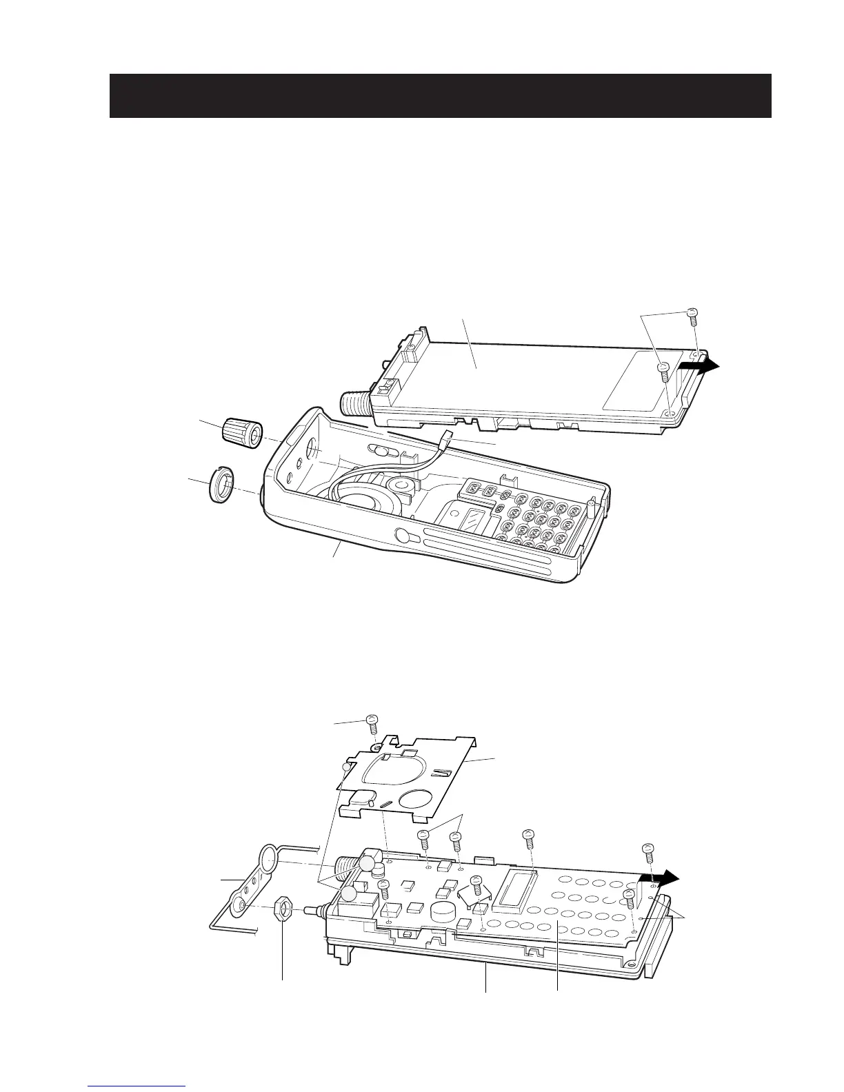
• Removing the chassis panel
q Unscrew 1 nut
A
, and remove 1 knob
B
.
w Unscrew 2 screws,
C
.
e Take off the chassis in the direction of the arrow.
r Unplug J6 to separate front panel and chassis.
• Removing the MAIN unit
q Remove the sealing rubber.
w Unsolder 3 points
D
and unscrew 1 nut
E
.
e Unscrew 2 screws,
F
, and 6 screws
G
(silver, 2 mm), to separate the chassis and MAIN unit.
r Take off the MAIN unit in the direction of the arrow.
Chassis
C
(nickel, 2 mm) × 2
J6 (Speaker connector)
Front panel
A
Nut
B
Knob
F
(black, 2 mm) × 2
Guide holes
Shield cover
(IC-F4/F4S only)
G
G
MAIN unit
Sealing rubber
E Nut
Chassis
G
G
G
D
G
(silver, 2 mm) × 6

Questions and Answers:

Question and Answer IconNeed help?

Do you have a question about the Icom IC-F4 and is the answer not in the manual?

Icom IC-F4 Specifications

General IconGeneral
BrandIcom
ModelIC-F4
CategoryTransceiver
LanguageEnglish

Related product manuals