7
2
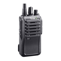
PANEL DESCRIPTION
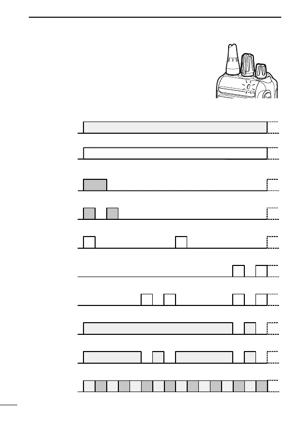
■ LED indicator
The LED indicator indicates the status of various
parameters of the transceiver as follows;
(Ref.; R=Red, G=Green, O=Orange)
R* R*
R* R* R* R*
O
O O
G G G G
G G
G G G G G G G G
R G R G R G R G R G R G R G R G
R O R O R O R O R O R O R O R O
G
G G
Clone Err
Clone TX/RX
Low BATT1
Low BATT2
Busy
F/S Scan
Call LED Blink
Call LED ON
TX Low BATT1
R*
• TX: Lights Red while transmitting a signal.
• RX: Lights Green while receiving a signal.
• Call LED (ON): Turns ON while receiving a matched 2/5-Tone.
• Call LED (Blink): Blinks while receiving a matched 2/5-Tone.
• Fast/Slow scan: Blinks when the Fast/Slow scan is activated.
• Low Battery 1: You should charge the battery. (blinks slowly)
• Low Battery 2: You must charge the battery. (blinks fast)
• TX low Battery 2: Very Low Battery was detected during TX mode.
• Channel Error: A non-programmed channel is selected.
* Lights (or blinks) orange when the optional battery case is attached.
• TX low Battery 1: Low Battery was detected during TX mode.
 Loading...