5 - 1
SECTION 5 ADJUSTMENT PROCEDURES
5-1 PREPARATION
■ REQUIRED TEST EQUIPMENT
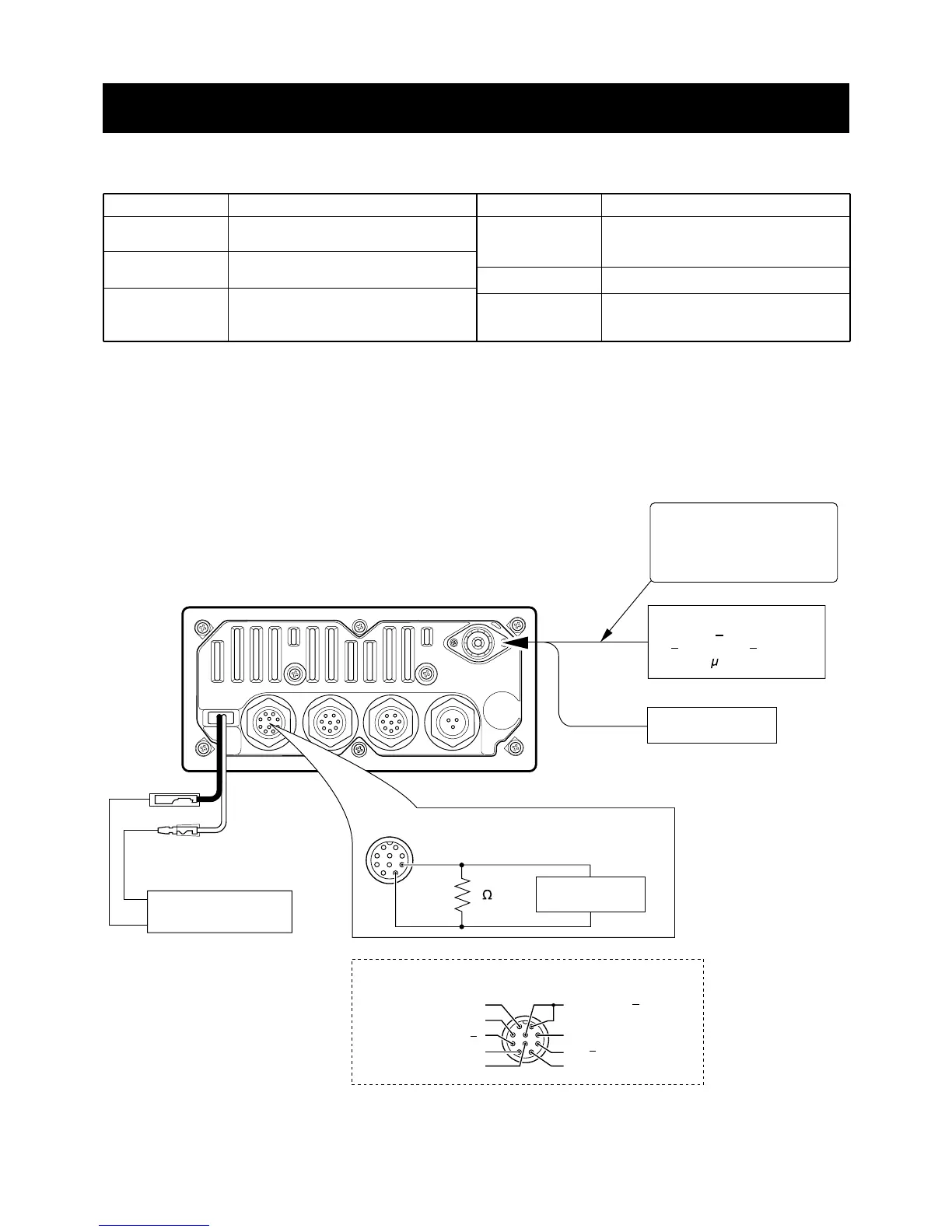
■ CONNECTION
EQUIPMENT
DC power supply
External speaker
Tracking generator
GRADE AND RANGE
Output voltage : 13.8 V DC
Current capacity : 10 A or more
Input impedance : 4 Ω
Capacity : 5 W or more
Frequency range : 100–300 MHz
Output level : 0.1 µV–32 mV
(–127 dBm to –17 dBm)
EQUIPMENT
Standard signal
generator (SSG)
DC voltmeter
Distortion meter
GRADE AND RANGE
Frequency range : 0.1–300 MHz
Output level : 0.1 µV–32 mV
(–127 to –17 dBm)
Input impedance : 50 kΩ/V DC or better
Frequency range : 1 kHz
±10 %
Measuring range : 1–100 %
 Loading...