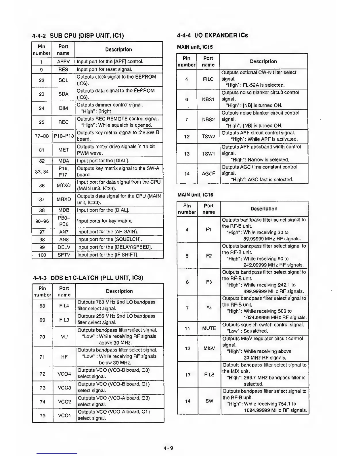
4-4-2
SUB CPU (DISP UN!T,
IC1)
Pin
Port
Description
number
name
1
APFV Input
port for
the
[APF] control.
9 RES
Input port for
reset signal.
22
SCL
Outputs
clock signal
to
the EEPROM
(IC6).
23
SDA
Outputs
data signal to the EEPROM
(IC6).
24
DIM
Outputs dimmer control
signal.
"High":
Bright
25 REC
Outputs REC REMOTE
control signal.
“High": While squelch is opened.
77-80 P10-P13
Outputs key
matrix signal to the SW-B
board.
81
MET
Outputs
meter drive
signals in 14 bit
PWM
wave.
82
MDA Input
port for the [DIAL].
83,
84
PI
6.
P17
Outputs
key matrix signal
to
the SW-A
board.
86
MTXD
Input port
for
data
signal from the
CPU
(MAIN unit, IC33).
87
MRXD
Outputs data
signal for the CPU (MAIN
unit, IC33).
88
MDB
Input port for the
[DIAL].
,
90-96
PBC^
PB6
Input
ports
for
key
matrix.
97 AN7
Input port for
the
[AF
GAIN].
98
AN8
Input port for the [SQUELCH].
99
DELV Input
port for the [DELAY/SPEED].
100
SFTV Input port for the jlF SHIFT).
4-4-3
[3DS
ETC-LATCH {PLL UNIT, IC3)
Pin
number
Port
1
name
Description
68
FIL4
Outputs 768
MHz
2
nd
LO
bandpass
filter select signal.
69
FIL3
Outputs 256 MHz 2nd LO bandpass
filter select
signal.
70
VU
Outputs
bandpass tilter*select signal.
“Low" :
While receiving
RF
signals
above
30
MHz.
71
HF
Outputs bandpass filter select signal.
"Low" :
While receiving RF signals
below
30
MHz.
72 VC04
Outputs
VCO
(VCO-B
board.
Q3)
select signal.
73
VC03
Outputs
VCO
(VCO’B
board.
Q1)
select
signal.
74 VC02
Outputs VCO
(VCO-A board.
Q3)
select signal.
75
VC01
Outputs VCO
(VCO-A board.
Q1)
select
signal.
4-4-4
I/O EXPANDER ICs
MAIN unit, IC15
Port
name
Description
FILC
1
Outputs
optional CW-N filter
select
signal.
“High": FL-52A is
selected.
NBS1
Outputs noise
blanker circuit control
signal.
"High": [NB] is turned ON.
NBS2
Outputs noise blanker circuit
control
signal.
“High”:
[NB]
is turned ON.
TSW2
Outputs APF circuit control
signal.
"High"
:
While APF is
activated.
TSW1
Outputs
APF passband width control
signal.
"High”: Narrow is selected.
1
AGCF
Outputs AGC
time constant control
signal.
"High": AGC
fast
is
selected.
MAIN unit, IC16
Port
name
Description
F1
Outputs
bandpass filter select
signal to
the RF-B unit.
“High":
While
receiving 30 to
89.99999
MHz RF signals.
F2
Outputs bandpass
filter select signal to
the RF-0 unit.
“High": While
receiving
90 to
242.09999
MHz RF
signals.
F3
Outputs
bandpass filter
select signal to
the RF-B unit.
"High”: While receiving 242.1
to
499.99999 MHz RF signals.
F4
Outputs
bandpass filter select signal
to
the RF-B unit.
“High": While receiving
500
to
1024.99999 MHz RF
signals.
MUTE
Outputs
squelch switch control signal.
"Low"
:
Squelched.
MI5V
Outputs
MI5V regulator circuit
control
signal.
"High”: While
receiving above
30 MHz RF signals.
FILS
Outputs bandpass filler select signal to
the MIX unit.
“High":
266.7
MHz
bandpass filter is
selected.
SW
Outputs
bandpass filter select signal to
the RF-B
unit.
"High": While receiving 754.1
to
1024.99999 MHz RF
signals.
 Loading...