34
ELECTRICAL CONNECTIONS
WARNING. This appliance MUST be earthed.
A mains supply of 230 V ~ 50 Hz is required.
All external controls and wiring MUST be suitable for mains
voltage.
The fuse rating should be 3 A.
Wiring external to the boiler MUST be in accordance with the
regulations.
0.75 mm
2
(24 x 0.2mm) and to BS. 6500, Table 16.
electrical installations.
Connection must be made in a way that allows complete
isolation of the electrical supply - such as a double pole switch
having a 3mm (
1/8”) contact separation in both poles, or a
plug and socket serving only the boiler and system controls.
The means of isolation must be accessible to the user after
installation.
35
INTERNAL WIRING
A pictorial wiring diagram is shown in Frame 40.
1. Route the mains cable via the rear of the boiler through the
grommit at the left hand side.
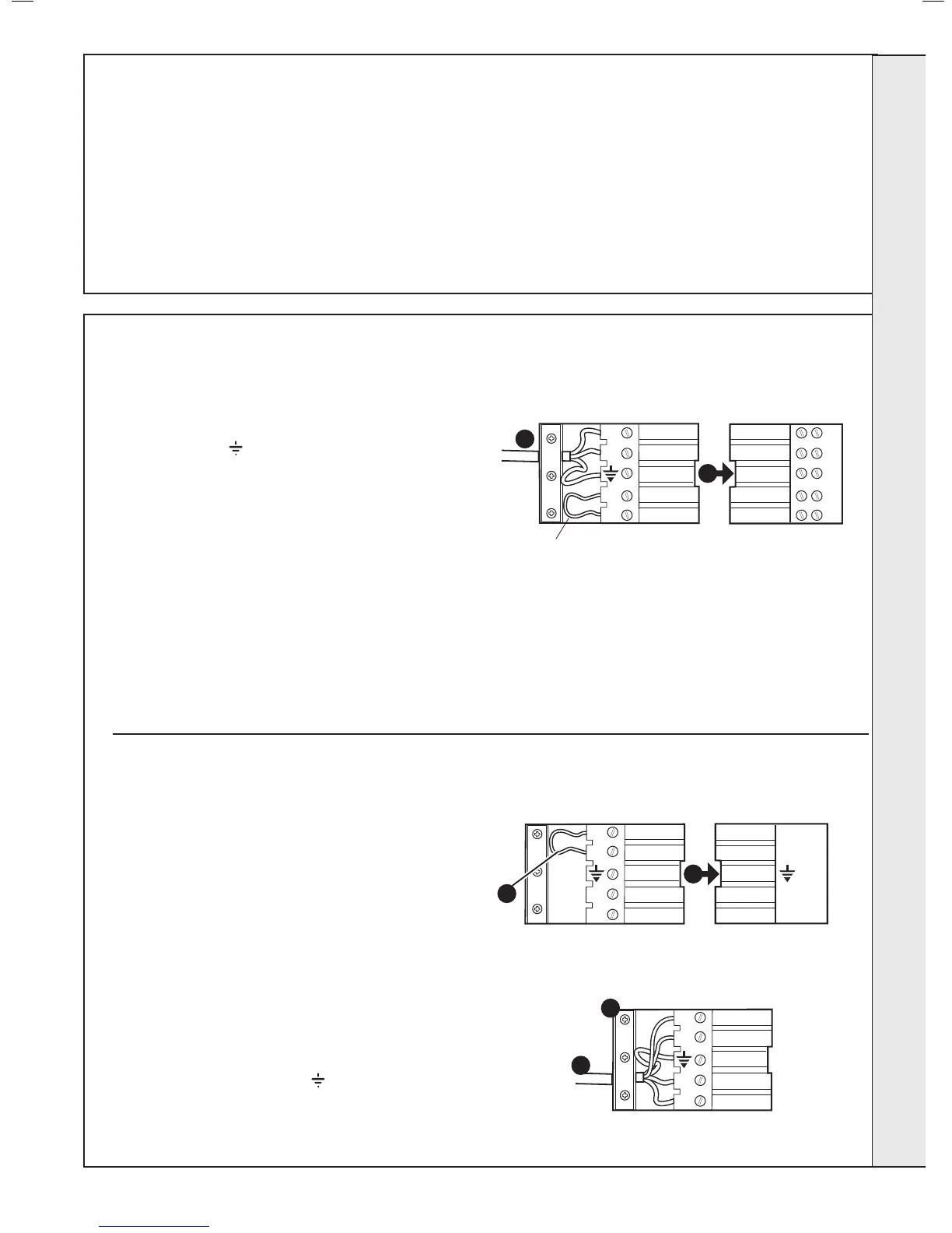
2. Wire the permanent live supply into the 5-way remote plug
terminals, L3, N &
.
IMPORTANT.
A permanent live is in order for the advanced
diagnostic controls to function correctly.
Ensure that the lengths of the live and neutral wires are shorter
than the earth wires so that if the cable slips in its anchorage
the current carrying wire become taut before the earth wire.
3. Wire any switched live supply into L2 or connect L1 and L2
via external control switching as shown in Frame 39. In either
4. Secure the mains lead with the cable clamp.
5.
into the socket.
If a condensate pump is to be tted
1. Route the cable via the rear of the boiler through the
grommit at the left hand side.
2. Remove the condensate pump plug from mating connector.
3. Remove wire link between L1 and L2.
4. Wire in condensate pump as shown below.
5. Secure cable sheath in cable clamps.
Ensure that the lengths of the live and neutral wires are shorter
than the earth wires so that if the cable slips in its anchorage
the current carrying wire become taut before the earth wire.
 Loading...