6
Concord CX - Installation
GENERAL
POSITION OF BOILER
Minimum clearances
required from walls or
other fixed objects to allow
for the free access of
combustion air are shown
in Table 3 above.
However, for maintenance
purposes we suggest a
minimum rear clearance of
50mm.
Any combustible material
adjacent to the boiler and
its flue system must be so
placed or shielded as to
ensure that its temperature
does not exceed 65
o
C
(150
o
F).
MULTIPLE BOILER INSTALLATIONS
The minimum installation clearances must conform to the
dimensions given below:
CX 40, 50, 60, 70 & 80
Clearance between boilers = 50mm
Clearance at both ends of the multiple installation = 50mm*
CX 90 & 100
Clearance between boilers = 100mm
Clearance at both ends of the multiple installation = 100mm*
Rear clearance: sufficient clearance should be given
at the rear of the boiler for connection of gas and
water pipework.
*Additional clearance is required for access at either
end of the installation.
2
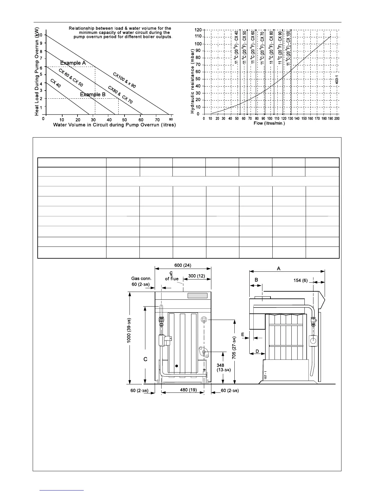
CLEARANCES & DIMENSIONS
Boiler Size CX 40 CX 50 CX 60 CX 70 CX 80 CX 90 CX100
No. of sections 3 4 4 5 5 6 6
Front clearance mm (in) 750 (29
1/2)
Rear clearance mm (in) 0 0 0 150 (6) 150 (6) 300 (12) 300 (12)
Side clearance mm (in) 50 (2) 50 (2) 50 (2) 50 (2) 50 (2) 100 (4) 100 (4)
Dimension A mm (in) 754 (
29 3/4
) 887 (
35
) 887 (
35
) 1047 (
41 1/4
) 1047 (
41 1/4
) 1217 (
48
) 1217 (
48
)
Dimension B mm (in) 108 (
4 1/4
) 108 (
4 1/4
) 122.5 (
4 7/8
) 122.5 (
4 7/8
) 135 (
5 3/8
) 190 (
7 1/2
) 190 (
7 1/2
)
Dimension C mm (in) 931.6 (
36 5/8
) 931.6 (
36 5/8
) 931.6 (
36 5/8
) 910.6 (
35 7/8
) 910.6 (
35 7/8
) 872.6 (
34 3/
8) 872.6 (
34 3/
8)
Dimension D mm (in) 177.5 (
7
) 187.5 (
7 3/8
) 187.5 (
7 3/8
) 224.5 (
8 7/8
) 224.5 (
8 7/8
) 271.5 (
10 5/8
) 271.5 (
10 5/8
)
Dimension E mm (in) 69.0 (
2 3/4
) 79.0 (
3 1/8
) 79.0 (
3 1/8
) 116.0 (
4 5/8
) 116.0 (
4 5/8
) 163.0 (
6 1/2
) 163.0 (
6 1/2
)
Table 3
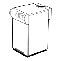
Graph 2 - Hydraulic Resistance
Graph 1 - Heat load / water volume
 Loading...