12" Min. - 24” Max.
[30.5 cm - 61 cm]
To Wall
12" [30.5 cm] Min.
Above Grade / Highest
Anticipated Snow Level
Vent Termination
12" [30.5 cm] Min.
Above Grade / Highest
Anticipated Snow Level
12" Min. - 24" Max.
[30.5 cm - 61 cm]
To Wall
36” Max.
[91.4 cm]
Vent Termination
27
CHAPTER 3
2. The combustion air piping must terminate at the
boiler with a 90º elbow.
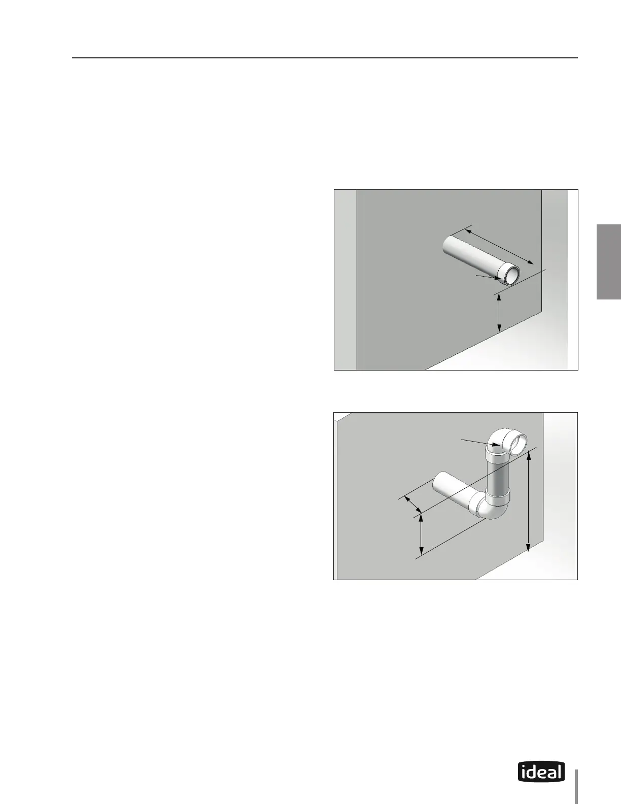
3. The vent piping can terminate:
• Using a coupling as shown in Fig. 18.
• Using a 90º elbow as shown in Fig. 19.
• The vent termination must be located 12”
[30.5 cm] minimum above grade / highest
anticipated snow level.
4. The following should be considered when
determining the location of the vent termination:
a. Locate the vent termination where ue vapors
will not damage surrounding shrubs, plants, air
conditioning equipment or be objectionable
to the homeowner.
b. The ue products will form a noticeable plume
of water vapor as they condense in colder air.
Avoid terminating the vent in areas where the
plume could obstruct window views.
c. Prevailing winds could cause freezing of ue
gas condensation and a buildup of water / ice
on surrounding plants or building surfaces.
d. Avoid locations where prevailing winds could
aect the performance of the boiler or cause
recirculation of the ue gases, such as inside
corners of buildings, near adjacent buildings,
vertical surfaces, window wells, stairwells,
alcoves, courtyards, or other recessed areas.
e. Do not terminate the vent above doors or
windows, ue condensate could freeze causing
ice formations.
f. Locate the vent termination to prevent possible
condensate damage to exterior nishes.
g. Avoid locations of possible accidental contact
of ue vapors with persons or pets.
5. The vent termination must also maintain the
following clearances; as shown in Fig. 16 on page
25 .
a. At least 3 feet [0.9 m] from adjacent walls
b. At least 3 feet [0.9 m] below roof overhangs
c. At least 7 feet [2.1 m] above any public walkways
d. At least 3 feet [0.9 m] above any forced air intake
within 10 feet [3 m] (Does not apply to the
combustion air inlet of a direct vent appliance).
e. No closer than 4 feet [1.2 m] below or horizontally
from any door, window or gravity air inlet.
f. Must be at least 4 feet [1.2 m] from any electric
meters, gas meters-regulators, relief valves or
other equipment. Never terminate the vent
above or below any of these items within 4
feet [1.2 m] horizontally.
g. A minimum 12 inches [30.5 cm] horizontal
spacing from other fan assisted appliance vents.
Never terminate the vent above or below any
fan assisted vent within 12 inches [30.5 cm]
horizontally.
CHAPTER 3 - CATEGORY IV (INDOOR AIR) INSTALLATION OF VENT/AIR PIPING
Fig. 18 - Category IV - Sidewall Termination of Vent Pipe
Fig. 19 - Category IV - Sidewall Snorkel Termination of Vent Pipe
 Loading...